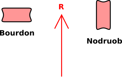
Figure 1: Basic Physics of the Bourdon Tube
A Bourdon tube is a way of measuring pressure. Probably every mechanical dial-type pressure gauge you’ve ever seen is based on a Bourdon tube. Our goal here is to understand the physics of how it works.
At first glance, a Bourdon tube is a curled-up metal tube. The base-end is held fixed while the tip-end is free to move. The tube tends to straighten out when pressure is applied to its inside. This means the tip moves. Via a mechanical linkage, the motion of the tip drives the indicator needle on the gauge.
If you look more closely, you discover that a cross-section of the Bourdon tube is nowhere near round. You could say that the tube has been flattened and then coiled up. The flattening turns out to be important, for the following reason: Any pressure inside the tube tends to un-flatten the cross-section. It pushes the two flat sides away from each other, making the cross-section more nearly round. This is the first step toward understanding why the tube straightens out.
Before we proceed further, let’s do a warm-up exercise. Consider the following secondary-school riddle: Suppose you wrap a cable around the equator of the earth. The cable is exactly the right length, so that it fits snugly. Then you wrap another cable around the equator. It follows nearly the same path as the first, except that this cable is six feet too long, so it does not fit snugly. You arrange that the excess length is evenly distributed all around the circumference. The question is, approximately how much of a gap is there between this cable and the ground?
The answer is that the second cable is everywhere about 1 foot off the ground. This comes as a surprise to some people, but we can understand it in terms of the simple formula
| (1) |
where R is the radius and L is the length of the cable. We can immediately deduce that
| (2) |
where ΔL is the “extra” length and ΔR is the “extra” radius.
More generally, if the cable goes only partway around the circle, we can write
| (3) |
You can see that equation 3 reduces to equation 1 in the case of a complete circle.
We now switch from talking about equatorial cables to talking about Bourdon tubes. The same equations apply, with almost the same interpretation.
In this new context, L is the overall length of the tube. Because the tube is curled up, the “outside” edge of the tube is longer than the “inside” edge, by an amount ΔL. Also, ΔR is the gap between the two flat sides of the cross-section. Meanwhile, R and/or θ can be used to describe how curled-up the tube is.
The same θ appears on both lines in equation 3, without any Δθ. This expresses the physical fact that the inner edge and outer edge start together, and also end together.
It must be emphasized that in all equations in this document, the Δ symbol refers to the change in a given quantity as we go from the inside edge to the outside edge of the tube. For example,
| (4) |
In particular, we do not use the Δ symbol to tell us anything about how R changes in response to pressure when we operate the Bourdon tube. To avoid confusion on this point, we rename the Δ-variables:
| (5) |
As a consequence of equation 3, using the new variables:
| (6) |
We can use equation 3 to eliminate θ from equation 6. That gives us
| (7) |
Note that the factor in square brackets is constant during normal Bourdon-tube operation, to a fair approximation. That’s because it is very much easier to flex a piece of metal than it is to lengthen or shorten it. We assume that the length L and the extra length x are “baked in” at the time the device is built.
Equation 7 tells us that when pressure causes the gap to increase, the radius of curvature of the curled-up tube must increase in proportion.
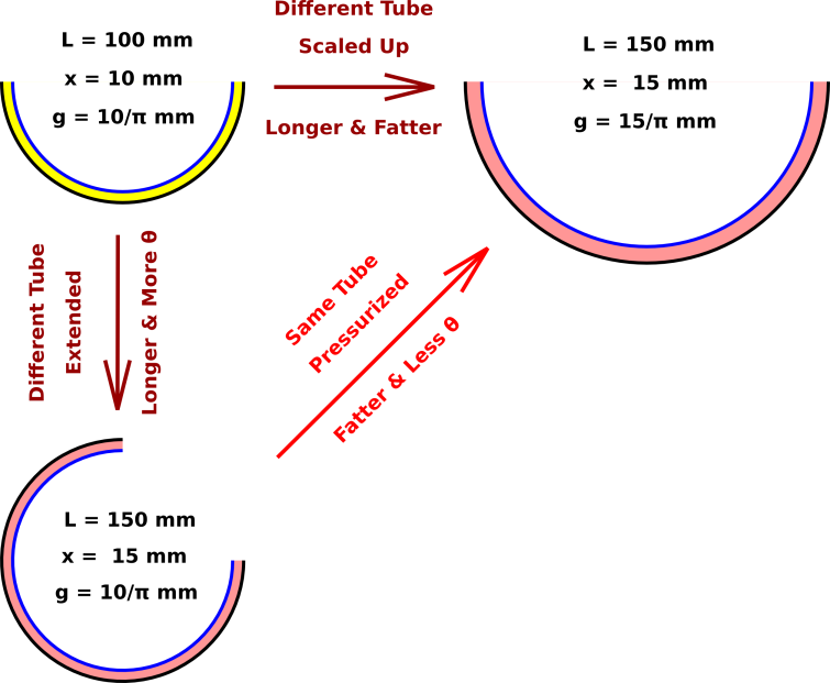
Let’s do an example, with numbers and pictures, as shown in figure 1. We start with the imaginary yellow tube as shown in the upper-left corner. If we make another tube using a longer piece of the same kind of tubing, we get the pink tube shown in the lower-left corner. It has 50% more length L, 50% more “extra” length x, and 50% more angle θ compared to the yellow tube. However, its gap g and radius R are unchanged relative to the yellow tube.
Another way to make the yellow tube bigger is just to scale it up in every direction, keeping the shape the same. This gives us the tube shown in the upper-right corner. It has 50% more length L, 50% more “extra” length x, 50% more gap g, and 50% more radius R compared to the original. The only thing that stays the same is the angle θ.
The interesting thing is that the upper-right tube can be considered the same tube as the lower-left tube, just with an increase in pressure. The length L is the same in both cases, as is the extra length x, so we are not trying to stretch the metal by brute force. The gap g has increased and the radius R has increased in proportion.
The analysis in section 1 can be considered a volume-based analysis. Pushing apart the inner and outer edges increases the internal volume of the tube, and we have shown how this results in an increase in the radius of curvature. It remains to connect this volume-change to pressure. This largely depends on the springiness of the cross-section. Previously we said it was relatively “easier” to flex the walls, but it is not infinitely easy.
Now that we understand what’s going on, we can make some interesting predictions.
For one thing, suppose we build a mutant Bourdon tube, flattened in the wrong direction, such that the side walls (parallel to the R vector) are close together, while the “inside” (small-R) and “outside” (large-R) edges are far apart, as shown in figure 2. We predict that such a tube will move the opposite way (compared to an ordinary Bourdon tube). Pressure will not cause it to straighten out; pressure will cause it to curl up. I call this a Nodruob tube.
Once upon a time I explained all this to a visiting professor who did not believe the prediction. We made a small bet. Then we went down to the shop and actually built such a thing. It’s slightly tricky to get the tube to curl in the unnatural direction, but we built a little jig that did the trick.
Treating the tube as having a more realistic cross-section, namely a flattened circle, would allow a much deeper and more accurate analysis. However, this would require quite a bit more mathematics, including fourth-order Green functions, elliptic integrals, et cetera.
In practice, you would probably learn more from thinking about the basic concepts and then doing a finite-element analysis ... rather than just staring at the equations.
A detailed analysis can be found in reference 1.