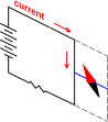
Figure 1: Compass and Turned-Off Electromagnet
As described in reference 1, once upon a time there was a kid named Pierre who was interested in the situation shown in in figure 1 and figure 2. The challenge is to explain why the second figure is not reflection-symmetric, even though first one apparently is. See reference 1 for a fuller discussion of why this is an interesting question.
There are basically only two possible answers:
Let’s deal with option #2 first. The fact is that the laws of electromagnetism are entirely reflection-symmetric. That comes as a shock to some people, because the laws are commonly written in a way that appears to be not reflection-symmetric. For example, to if you want to describe the magnetic field of a long straight wire using old-fashioned magnetic field lines, you need the right-hand rule.1 If you look at a mirror image of the apparatus, the right-hand rule gives diametrically opposite results.
The point remains that this apparent asymmetry is illusory. It is an artifact resulting from writing the equations in a clumsy way.2 It turns out that every observable prediction that the equations make involves an even number of applications of the right-hand rule, so that the second undoes the mischief done by the first.
So #2 is the wrong answer. As we shall see, #1 is the right answer.
The wrong answer can be seen to be wrong, and the right answer can be seen to be right, if we formulate the laws of electromagnetism in a better way – without using the right-hand rule. You cannot represent the magnetic field by a vector without using the right-hand rule, so we will represent it by a bivector. There are many, many reasons to believe this is the right thing to do.
A bivector can be represented as a patch of area, with a direction of circulation marked on it. A bivector is the next step beyond vector in a logical progression:
| scalar | point | no geometric extent | grade=0 |
| vector | length | geometric extent in 1 direction | grade=1 |
| bivector | area | geometric extent in 2 directions | grade=2 |
| trivector | volume | geometric extent in 3 directions | grade=3 |
| etc. | | | |
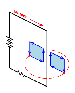
The bivector representing the magnetic field of a long, straight wire3 is shown in figure 3.
The field is shown at two points, one inside the loop and one outside the loop. The field is represented in this case by a rectangular area, although the shape of the area is unimportant. The direction of circulation of the bivector is such that the edge nearest the wire is directed oppositely to the current in the wire.4 As indicated by the red dashed circle, the field is rotationally symmetric, where the axis of symmetry coincides with the long, straight wire.5 The strength of the field falls off like 1/r, where r is the radial distance from the wire.
Note that the situation in figure 3 retains complete reflection symmetry. If you tried to represent the magnetic field by a vector, it would falsely suggest that symmetry had been lost.
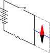
Our next task is to describe the magnetism of the compass needle. This is shown in figure 4. You should visualize the needle as wearing a belt with arrowhead markings on it.
Even though the metal of which the needle is made has a macroscopically symmetric shape, the magnetic field (when represented as it should be, by a bivector) does not have reflection symmetry. If you look at figure 4 in a mirror, the sense of circulation of the bivector is reversed.
Note that it is not necessary to paint one end of the needle red. The belt (with arrowheads) tells us everything we need to know about how the needle will respond to a magnetic field.
If you wish, you can imagine that the compass needle has microscopic current loops inside it, generating the observed field. This hypothesis was first put forward by Ampère, hence the name, Amperian currents. There aren’t loops in the usual sense, but there are a lot of spinning electrons all lined up the same way, and there is even angular momentum involved. In any case, it is absolutely true that the microscopic physics does have the symmetry (or lack thereof) indicated by figure 4.
The rule is simple: the needle will try to rotate so that its magnetic field (bivector) is aligned with the magnetic field (bivector) produced by the nearby wire.
If you continue down this road, representing the electromagnetic field as a bivector, you can solve all the equations of electromagnetism without using the right-hand rule.
One thing that you cannot do without using the right-hand rule (or the equivalent) is to decide which end of a magnet should be labeled “North”. Note that the needle in figure 4 has both ends colored the same.
Consider the following scenario: Take a bunch of steel needles, with colored ends. Demagnetize them. Give them to a color-blind friend, with instructions to magnetize them somehow and give them back. You will find that half of them have North on the red end and half of them are the other way around.
The interesting thing is that there is nothing in the laws of electromagnetism, or indeed all of classical physics, or even quantum electrodynamics, that will tell you which version is “right” and which version is “wrong”. The only ways to do it involve either
To create a chiral object, it needs to have a sense of circulation (i.e. a bivector), and one side of the bivector needs to be marked to distinguish it from the other side. If you have an area that is marked on one side but not circulating, it is not chiral. And if you have an area with circulation, but neither side is marked, it is not chiral.
FYI, the needles in figure 1 and figure 2 are marked in the conventional way, with the North end marked red.
English translation: “On symmetry in physical phenomena, symmetry of an electric field and of a magnetic field”