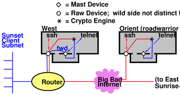
Figure 1: Gateway Routes Packets Between Subnets
Copyright © 2005 jsd
Next-Generation IPsec Packet HandlingJohn S. Denker |
How should we handle packets in an IPsec system? IMHO the best approach is to use a so-called "mast" device. It is similar to the ipsec device in the first-generation FreeS/WAN implementation (reference 1):
| === mast device === | === KLIPS-1 ipsec device === |
| Cleartext packets get routed to, and absorbed by, the mast device. | Cleartext packets get routed to, and absorbed by, the ipsec device. |
| The user MAY attach arbitrarily many tunnels1 to each mast device. | The user MAY attach arbitrarily many tunnels to each ipsec device. |
But there are important differences:
| Mast devices are logically independent of the system’s raw2 devices. | Each ipsec device is wedded to a particular raw device; there must be exactly one ipsec device per raw device if crypto packets are to be sent or received via that raw device. |
| There is often no need for more than one mast device, but the user MAY create arbitrarily many mast devices (which may simplify the expression of security policy or routing). | The number of ipsec devices is fixed at the time the ipsec module is compiled. The default is four. |
| The mast device is designed to play nicely with routers. | Routing issues didn’t receive much attention during the first-generation design process. |
The mast device is radically different from the approach taken by the KAME implementation of IPsec (reference 2) which doesn’t offer any notion of device. I have no idea what it would take to get KAME to play nicely with routers.
We need to discuss the advantages and disadvantages of the proposed design. Here is a down payment on such a discussion. This is a somewhat-biased report on 5 consecutive 18-hour days of work, including contributions from Hugh Daniel, Michael C. Richardson, Claudia Schmeing, Hugh Redelmeier, Richard Guy Briggs, Sandy Harris, and others. For some earlier thinking that provides a background to this work, see reference 3 and reference 4.
1) Having a mast device, and thinking of it as a device, provides users with a conceptual framework. People have certain expectations for how a typical device should behave. To the extent that the mast device exhibits typical behavior, it is easy for people to understand what it does. It is easy for us to document what it does.
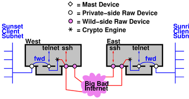
Getting absorbed by a device is the normal natural fate of packets that an application sends out. Figure 1 shows a typical network topology, and shows how the packets are routed between subnets, including the routing within the gateway. “Sunset” and “Sunrise” are the names of subnets. “East” and “West” are computers, IPsec hosts, serving as gateways.
Section 4 and section 5 discuss how the mast device plugs into the protocol stack.
2) Similarly it provides the designers with a conceptual framework, and serves as guide to the design. Concepts, documentation, and even code can be borrowed from standard device drivers.
There are certain standard questions that come up when building a device. The mast device forces us to address these questions, and in large measure suggests obvious answers. As an example: Everybody knows what it means for a device to lose its link to a peer (host unreachable). It’s obvious that routing daemons need to be notified when a link goes down, and there are standard methods for doing so. See rtnetlink(7).
We exploit this analogy as follows: A tunnel is a virtual link from one mast device to another. Such a link can go down for various reasons, notably including expiration of the security association. The mast device should notify routing daemons when this happens. (KLIPS-1, alas, doesn’t.)
Another way a virtual link can go down is if there is an outage below the tunnel layer, i.e. loss of the raw-IP links carrying the cryptotext packets. We would like the mast device to be notified of this (if possible!) so the affected virtual links can be marked as down.
Tangential Note: In some cases it is possible for the mast device to know what is happening at lower layers. For instance, if a local interface is unplugged from its PCMCIA slot we can know this with certainty. In contrast, in other cases it may be hard to get trustworthy information. ICMP messages are unauthenticated, so if we receive an ICMP message purportedly reporting a problem with a cryptotext packet, we don’t know whether to trust it or not. This is a fundamental gap in the IPsec architecture (reference 10). We can’t pretend the IPsec link is secure against a denial-of-service attack if it relies on raw-IP transport that is vulnerable. We need a consistent degree of protection.
3) We choose to think of the IPsec tunnel as creating a "virtually private" link. The semantics of such links is fundamentally similar to the more-familiar raw-IP links, but each instance may differ in details such as:
Implementing a mast device with the appropriate properties allows us to expose these properties to user-level applications as well as to routing daemons, et cetera. It provides compatibility with existing tools that read the routing table and try to make sense of it.
4) The mast-device concept allows us to recognize host-to-host mode as a natural special case of host-to-subnet mode. Similarly subnet-to-host mode is a natural special case of subnet-to-subnet mode. See section 6 for more on this.
Things are conceptually simpler if the mast device has its own default source address, distinct from any of the host’s raw devices. Sometimes this is absolutely necessary.
Consider the “crypto on a stub” topology shown in figure 2.
West advertises that it has a route to Sunrise-net via the IPsec tunnel. Clients on Sunset-net use this route as follows: The client emits a plaintext packet addressed to some peer over on Sunrise-net. The router routes the plaintext to West, because West is the only box that has an appropriate route. West absorbs the plaintext and produces a crypto packet. The crypto packet is addressed to the wild side of East, and this is expressed in the outer header of the crypto packet. The router sends it via the internet to East, no problem.
Things get much trickier if the plaintext is addressed to Orient, which is not a gateway but rather a singleton endpoint, doing IPsec on its own behalf only. It is crucial to realize that there are two different things that the client on Sunset-net might intend when it sends a packet. It might intend the packet to be routed to the wild side of Orient, bypassing the crypto stub. Or it might intend the packet to be encrypted.
Note that we know how to do ESP if it stands for Encapsulated Security Payload. We don’t know how to do Extra-Sensory Perception. The router cannot read the mind of the originator to find out what was intended; it can only look at IP addresses. Therefore the mast device on Orient simply must have a different address from the wild device.
If Orient uses the same address for both, you are just begging to have router loops. KLIPS-1 contains special trickery to prevent loops within the West machine itself, but this protection does not extend beyond the boundaries of the West box. In particular, it does not extend to the router in figure 2.
This should convince you that a mast device needs its own IP address. We call this the private-side address as opposed to the wild-side address of the raw-IP device. (Some IPsec vendors call the private-side address a “virtual” IP address.)
If you need additional convincing, see section 6.2.
We do not require the private-side address to be a “private” address in the sense of reference 9. In many cases there are good reasons for using an ordinary IP address that can be advertised in public. However, in some places there are alleged shortages of available IP addresses, so we need the mast device to work even if an ordinary address is not readily available. There are several ways of dealing with this:
For the somewhat esoteric case of IPsec transport mode, see section 6.1.
Much effort has gone into what is commonly called "Opportunistic Encryption". IMHO the name is misleading. The word “opportunism” has mostly negative connotations. What is really wanted is scalable extemporaneous encryption, “on demand” with minimal pre-arrangement. We need to make it easy to get started for small-time operators, and to make things scale properly for big-time operators.
Current designs require users to have control of the forward and reverse DNS for "the" IP address of their IPsec box. Alas, this control is often hard or impossible to obtain.
The notion of a mast device – with its own IP address – may make things much better. It should suffice for the user to have control of the DNS for the private-side addresses. This should be incomparably easier to arrange than for the wild-side addresses.
One often hears about the Open System Interconnect (OSI) layer model, also called the protocol stack. The question arises, “Where does IPsec fit into the protocol stack ”.
Before answering the question, let’s remind ourselves what the stack looks like. It has seven layers, as described below. We are particularly interested in layers 2, 3, 4, and 7:
When ether is used to transport an IP packet, the frame that moves on the wire has both a 48-bit layer-2 ether address (on the outside) and a 32-bit layer-3 IP address (on the inside, as the client of the ether packet). Each of those addresses plays an important role, and this sheds light on the design of the mast device. So let’s look at this more closely.
You might be tempted to think that the IP address is what matters, so why not just forget about the 48-bit layer-2 ether address (also called MAC address); just throw the IP packet onto the ether and let the recipient(s) sort it out based on the IP address. But that wouldn’t be right.
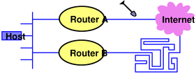
The importance of the layer-2 MAC address can be seen in figure 3. Suppose an IP packet is sent from the indicated host to some destination in the internet cloud. The packet has a definite layer-3 IP address. But how does it get routed? Let’s suppose router A has the most direct route, so ordinarily the packet should get routed via router A and not router B.
One fine day, however, the farmer in the dell cuts the link between router A and the internet, at the point indicated by the shovel in the diagram. Until the cut is repaired, we want packets from our host to be routed via router B. It has a somewhat tortuous connection to the internet, but that’s better than nothing.
Our host is running a routing daemon. The daemon’s job is to notice the change in connectivity and update the host’s routing table accordingly. On a packet-by-packet basis, the host uses the routing table to decide what layer-2 MAC address to put on the packets. If the routing table says to use router A, the host will ARP router A and use the resulting layer-2 MAC address. If the routing table says to use router B, the host will ARP router B and use that layer-2 MAC address. The layer-3 IP address remains the same; it is not affected by the change in routing.
The analogy to mast devices goes like this: A single mast device MAY have multiple tunnels connected to it. The far end of each tunnel is connected to a destination subnet. These destination subnets may be disjoint, in which case life is simple ... but we must consider the case where they are not disjoint, i.e. overlapping or even identical. There are good reasons for non-disjoint destination subnets, including fault tolerance in analogy to figure 3, mobility, and load-sharing to improve throughput.
It is easy to see how to handle this situation. We treat the mast device as a multi-access device just like ether (but without ether’s broadcast and multicast features). This is called NBMA – Non-Broadcast Multi-Access. When an IP packet arrives at the mast device, we must consult the routing table(s) before we can figure out what to do with it. Tunnel ID numbers play the role corresponding to MAC addresses.
If there are two tunnels with equal routing metric, the kernel can do equal-cost multipath routing, thereby improving throughput via load-sharing. Tunnels may come and go, or change their metrics, due to expiration of SAs, negotiation of new SAs, or disturbances in the underlying raw-IP links that carry the IPsec packets. Keepalives or other means may be used to check the health of tunnels.
This picture stands in stark contrast with KLIPS version 1, which has no concept of addressing other than layer-3 IP addressing, so it has no chance of implementing multiple routes to the same destination subnet.
Conclusion: When cleartext IP packets are delivered to the mast device, the mast device behaves in many ways like an NBMA device. It has layer-2 features analogous to MAC addresses.
We now return to the question, “Where does IPsec fit into the protocol stack ”.
Back in the mists of antiquity, it was thought that IPsec lived entirely within layer 3: as its name implies, IPsec deals with IP packets, and the thinking was that IPsec just applied a slight transformation to packets that were going to be sent anyway.3 This might (barely) describe transport mode, but fails miserably for tunnel mode. No tunnel (cryptologic or otherwise) can fit into the stack at any single layer.
We are taking the view that tunnel mode is primary and fundamental. (Transport mode can be considered a slight optimization, applicable in special cases; see section 6.1.
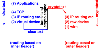
Any tunnel must be both below layer 3 and above layer 3.
Therefore you should think about IPsec in terms of an “elevator” model, as shown in figure 4. ISO layer numbers are shown in parentheses. We see that IPsec connects to the stack in two places. It accepts and absorbs cleartext packets below layer 3, carries the information upstairs during processing, and injects cryptotext packets above layer 3.
We should explain how the mast device handles IPsec transport mode. This mode was intended to be used in case where both ends of the IPsec connection are singleton endpoints (as opposed to gateways serving subnets). In this case the private-side source address and private-side destination address are known implicitly, and need not be represented in the “inner header” in the IPsec packet that is sent down the wire.
In the prior art it has been tacitly assumed that in transport mode, each private-side address must be identical to the corresponding wild-side address. But we hereby point out that this is not a requirement! When our box is running IPsec-ng and has a transport mode connection to peer of any kind (IPsec-ng or not), we can arbitrarily assign a private-side address to our mast device, and (!) we can arbitrarily impute a private-side address to the peer.
If both ends of the connection support this scheme, they can negotiate an agreement as to what private-side addresses to use. If they fail to agree (perhaps because one end is ignorant of the scheme), the scheme still works nicely at our end. In this case it is tantamount to having our end perform network address translation (NAT) on the cleartext packets. For an incoming packet the source address is constructed to match the peer’s private-side address, while the destination address is constructed to match our private-side address. For an outgoing packet we don’t need to think too hard, since whatever addresses appear on the cleartext packet are stripped off, not represented on the wire at all. The peer will construct addresses when the packet is received, probably setting them equal to the corresponding wild-side addresses, but that’s not our problem.
One advantage of this scheme is that it allows applications on our end to express whether they want to send packets “as is” (addressed to the peer’s wild-side address) or to send them with IPsec encryption added (addressed to the peer’s private-side address). The biggest beneficiaries are the keying and encryption mechanisms themselves, because they need to be able to send IKE and ESP packets to the wild side of the peer. This scheme gives us a non-kludgey way to avoid routing loops.
There are a few applications that don’t tolerate NAT, typically because they put IP addresses in application-layer data. If such applications are important to you, use IPsec tunnel mode, to ensure that everybody agrees about the private-side addresses. If you really want to use transport mode, use IPsec-ng on both ends, so they can negotiate an agreement about the private-side addresses. (Such negotiations require an extension to the IPsec rfc, reference 10.)
If you want interoperable transport mode with no NAT, it is theoretically possible to support this; IPsec-ng and Pluto would need to use nfmark and other iproute2 features to prevent routing loops, since the mast device would be forced to have the same address as the raw device in this case. This is possible in theory, but it probably won’t be implemented.
If you insist on using a non-IPsec-ng peer, insist on transport mode, insist on no NAT, and insist on not running iproute2, that’s definitely not going to be implemented by IPsec-ng. Stick with KLIPS-1 in that case.
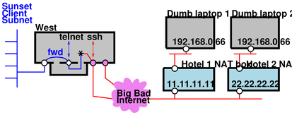
Another advantage of imputed private addresses (pointed out by Jim Carter) is that it allows us to handle the situation diagrammed in figure 5. The key element here is NAT applied to each laptop’s wild interface; this is not to be confused with NAT applied to the private side.
This situation is probably unusual; most IPsec implementations that are smart enough to perform NAT traversal are also smart enough to assign themselves a private-side address distinct from their wild-side address.
But let’s just suppose the laptops insist on setting their private-side address equal to their wild-side address. In this scenario it doesn’t matter whether they are using transport mode (host to host) or tunnel mode (subnet to host) as diagrammed in figure 5.
What address shall we use when the telnet application on West wants to talk to Laptop 1? We can’t use laptop’s wild-side address, because that conflicts with Laptop 2. We can’t use Hotel 1’s address, because that would conflict with any other road warriors in the same hotel. The only solution is for West to arbitrarily invent an address and impute it to Laptop 1’s private side. And similarly for Laptop 2, et cetera.
Copyright © 2005 jsd