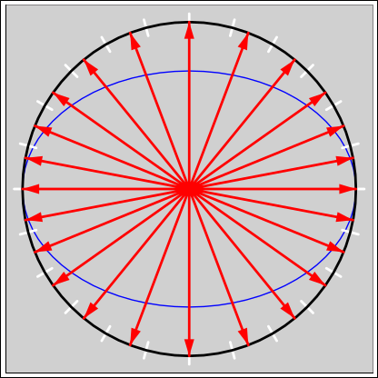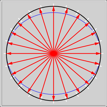
Figure 1: ADF Error : 30∘ Bank
Once upon a time, the Automatic Direction Finder (ADF) was the primary navigation instrument in an aircraft. However, that was a long time ago. NDBs were largely supplanted by VORs, and VORs are rapidly being supplanted by GPS, for both enroute navigation and for instrument approaches. Nowadays anybody who can afford an aircraft can afford a GPS receiver.
On the other hand, NDBs and NDB approaches still exist, especially in less-heavily-populated areas. Also, the GPS system is in some ways quite fragile, and there are lots of ways that the GPS signal can become unusable. So at least for now, ADF skills are worth having.
An ADF has a number of operational problems, including
For a terse but correct overview of the principles of operation, see reference 1.
Bank error is diagrammed in figure 1 for the case of a 30 degree bank angle. The red arrows are evenly spaced every 15∘ in terms of of the true relative bearing to the station. However, due to bank error, they are not evenly spaced in terms of indicated relative bearing. The white tick marks correspond to the correct, evenly-spaced relative bearings. The blue curve indicates the sensitivity of the instrument, relative to the unbanked condition.
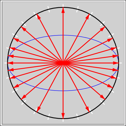
Figure 2 and figure 3 show the same information for larger bank angles.
To say the same thing another way, the needle will move too slowly when it is near 3:00 or 6:00, and will move too quickly when it is near 12:00 or 6:00.
This can have operational significance if you are looking at the ADF needle to check your progress while turning to intercept an NDB radial. It can trick you into rolling out too late. The effect is not very large during normal manuevers; for example, in a 30∘ banked turn, the ADF needle can be off by a little more than 4 degrees.
In a 45∘ bank, the error can be almost 10 degrees. In a 60∘ bank, the error can be almost 20 degrees. For very large bank angles, as in figure 5, the ADF can be in error by as much as 90 degrees. However, when the bank angle is that large, you probably aren’t paying attention to the ADF needle.
Bank error is intrinsic to the design of any ordinary ADF instrument. There can be additional non-intrinsic attitude-dependent errors depending on details of how the antennas are installed, since the signal can be affected by the structure of the aircraft.
In this document, from now on, we focus on intrinsic bank error to the exclusion of other possible errors.
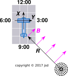
Let’s build an analog model. Arrange a comb so it extends past the edge of a table or desk. Set a book on it to hold it in place if necessary. The comb is represented by the S and B vectors in figure 4. The spine of the comb represents the radial S from the station to the aircraft. The tines of the comb represent the B-vector, which is everywhere horizontal and everywhere perpendicular to the radial.
There is an important and non-obvious bit of physics in the last sentence. The ADF antenna responds to a field that is perpendicular to the radial. The instrument does a fair bit of work internally to rotate that 90∘ so it can display the radial.
Take a 3×5 index card and sketch an airplane on it. Label the X-axis (toward the nose) and the Y-axis (toward the starboard wingtip). Start with the card in level flight attitude, located at the end of the comb. Yaw it so that the relative bearing is 45∘. We shall be particularly interested in the last tine, i.e. the one at the location of the aircraft. It will be oriented 45∘ relative to the X-axis and also 45∘ to the Y-axis. That means the B-vector has both an X-component and a Y-component. So far nothing tricky.
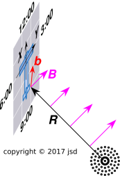
Now bank the airplane almost 90∘. That is, roll it around its own X-axis, keeping the X-axis fixed. The new situation is shown in figure 5. The last tine has the same X-component as before. However, the Y-component is now almost zero. There is a large Z-component, but the ADF instrument is not sensitive to that.
If we discard the Z-component, keeping only the X- and Y-components, we get a vector b in the plane of the card. This called projecting the vector onto the XY plane. The ADF instrument is sensitive to the b vector. In figure 5, it points to a little past 12:00. That means the ADF needle will point to an errorneous relative bearing a little past 3:00.
Note that back in figure 4, the b vector was the same as the B vector. It pointed to 1:30, so the ADF instrument indicated the correct relative bearing of 4:30.
Let’s analyze the situation more quantitatively.
First, construct the vector S from the station to the aircraft. Presumably we know the position of the aircraft and the position of the station in the earth-centered earth-fixed (ECEF) frame. Subtract them to obtain S. (For more about coordinate systems, see reference 2 and references therein.)
| (1) |
Establish a NED (North-East-Down) coordinate system at the site of the NDB transmitter. Convert S to this coordinate system.
The NDB antenna is vertical, which means that the E-field in the NE plane is vertical, and the wave is said to be vertically polarized. However, we care about the B-field, which will be everywhere horizontal (in the NED frame) and everywhere perpendicular to S.
In figure 4, the station is at 4:30 and the B vector points toward 1:30.
In more detail: Project S onto the NE plane. That is, throw away the SD component. Then rotate the projection by 90∘ in the horizontal (NE) plane; this gives us a vector Bdir that is in desired direction, i.e. the same direction as the B, but with some unknown magnitude.
| (2) |
Divide by |Bdir| to obtain a unit vector Bunit in the desired direction.
| (3) |
We now compute |B|, i.e. the magnitude of B. Assume we know the radiated power P of the signal. Take the square root. This converts power to voltage. Then the magnitude of the B-field at some distant point is:
| (4) |
where θ is the angle of elevation. The factor of cos(θ) accounts for the dipole radiation pattern. In aviation terms, it accounts for the cone of silence directly above the station. As a function of distance, the voltage scales like 1/|S|.
Multiply this |B| by the aforementioned Bunit to obtain the full B vector.
| (5) |
We now introduce the conventional XYZ axes attached to the body of the aircraft. The ADF receiver’s loop antenna cares about the projection of the B vector onto the XY plane.
If I were doing it, I would convert the B vector from the NED frame to the earth-centered earth-fixed (ECEF) frame at this stage, for reasons to be discussed in the next paragraph.
Next, convert the B vector into the XYZ frame attached to the body of the aircraft. We do this in two stages (NED to ECEF to Body), because if you’re not careful a direct transformation from NED to Body will use the NED frame at the aircraft’s location, but we want it to use the NED frame anchored at the NDB station. The ECEF frame gives us more control over such anchoring issues.
This conversion is just a rotation of the vector. In particular, if you have the aircraft attitude as a quaternion q in the ECEF frame, apply the rotation −q to the B vector.
To calculate the projection onto the XY plane is now trivial: just throw away the Z component. This gives us the lower-case b vector.
Rotate the b vector 90∘ in the XY plane to get something that points to the station (in level flight).
At this point, you can add some noise to the bX and and bY components, to model the system’s signal-strength requirements.
If you want the relative bearing as an angle, apply the atan2(,) function to the components of the b vector.
Then add some slew-rate limiting. The needle’s travel toward the right answer is slew-rate limited.
It is recommended to push the TEST button every so often. That causes the ADF needle to slew clockwise. Then release the button and see how fast it returns to the previous bearing. If it returns slowly or not at all, it means the signal is marginal or worse.
That is to say, if the observed response is not slew-rate limited, the instrument doesn’t know what it’s doing.
As long as the pitch and bank angles are small compared to 90∘, you can skip this section. On the other hand, if you like to fly NDB approaches inverted, you need worry about the sense antenna.
It receives the E-vector. This is in contrast to the loop antenna discussed in section 4, which receives the B-vector. The loop antenna by itself cannot tell the difference between any given heading and its reciprocal. The sense antenna is needed to disambiguate the two possibilities.
In inverted flight the voltage picked up by the sense antenna will be reversed.