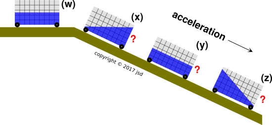
Figure 1: Accelerated Tank Car
The equivalence principle has considerable practical value. It provides a quick, simple, and reliable way of understanding situations that might otherwise seem complicated and confusing. Some examples are presented below.
Consider the “tank car” shown in figure 1. You can make such a thing by attaching a “liquid accelerometer” to an ordinary dynamics cart. (See reference 1, reference 2, and section 5.)
At location (w), the cart is rolling horizontally at constant velocity. At locations (x), (y), and (z), the cart is accelerating down the ramp under the influence of gravity. The question is, in which of the diagrams – (x), (y), and/or (z) – is the equilibrium position of the blue liquid shown correctly?
There is an elegant way to answer this question. It illustrates some modern (post-1915) physics, namely the equivalence principle and the idea of accelerated reference frames. This is not the only method of solution, and nobody is obliged to use if if they don’t want to. However, it serves as a powerful check on whatever other method(s) might be used.
In the frame comoving with the liquid, the only significant force is normal to the ramp. At equilibrium, the liquid surface will be perpendicular to this force, i.e. parallel to the ramp, as in diagram (y).
We start with the rule of thumb that says, pick a frame of reference that makes the physics look simple. In a great many situations, a freely-falling frame is simple, because it means we don’t need to worry about the local gravitational field. For example, as you sit in your chair, you are being accelerated skyward at 9.8 m/s/s relative to any nearby freely-falling frame. The floor pushes up on the chair, and the chair pushes up on you.
This is a rather direct application of the equivalence principle: Locally, to first order, a gravitational field is indistinguishable from an accelerated reference frame.
We can apply this immediately to the cart in the case where the ramp is vertical. The cart is freely falling. In any freely-falling frame, the cart is weightless and the liquid is weightless. Depending on details (i.e. various surface tensions and wetting angles) the water might bunch up in blob, somewhere in the middle of the available region.
Next we apply this when the ramp has some finite slope. To a decent approximation the only force on the cart (in any freely-falling frame) is the normal force from the ramp. (There is a correction term due to the rotational moment of inertia of the wheels. There are also various correction terms due to friction. However, we assume these are all small.)
We now switch to the frame comoving with the cart. This is not a freely-falling frame. There is a gravitational field, aligned in the direction perpendicular to the ramp – not aligned with the laboratory up/down direction. The equilibrium water surface will be perpendicular to the local gravitational field. This is to be expected, always, in any frame where gravity produces the only relevant force. Gravity means acceleration of the reference frame. Perpendicular to the normal force implies parallel to the ramp.
Note the contrast:
| Everything up to this point has focused on the equilibrium situation where the tank-car is undergoing steady, uniform acceleration. | If there is some jerk, i.e. some non-steady acceleration, the fluid will slosh in complicated ways. |
Therefore we require some dissipation, so that any initial sloshing dies out, allowing us to observe the equilibrium state. In practice we rely on viscous damping in the fluid. This is part of the design of the apparatus, as mentioned in section 5.
One might also ask what happens if the cart moves down the ramp at constant velocity. Operationally, eddy currents are a good way to achieve highly reproducible, steady braking.
Suppose we have a liquid-fuel rocket, parked in orbit, inactive for the moment. The fuel tank is only about half full. You can use any reference frame you like, but it is particularly convenient to use the frame comoving with the rocket. In this frame, the fuel is weighless. The dominant force on the fuel is surface tension. Depending on the various wetting angles involved, it is entirely possible that the fuel sticks to itself better than it sticks to anything else, in which case it will bunch up in a blob in the middle of the tank somewhere. In general, it can be quite tricky to arrange an outlet that actually connects to the liquid. The usual practical solution is to use an ullage motor, which is a small auxiliary rocket motor with its own carefully-engineered fuel supply, and is used to apply a small acceleration to the overall spacecraft, so that the fuel gravitates to the part of the tank where the outlet is.
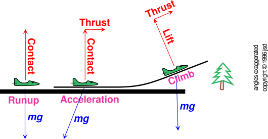
Consider the situation shown in figure 2. During the takeoff roll, relative to any freely-falling frame, the aircraft is being accelerated upward (by the ground in contact with the wheels) and also accelerated forward (by the thrust). Therefore the g vector, in the frame comoving with the aircraft, is oriented down and back relative to the terrestrial lab frame. Of course in the aircraft frame, g is oriented down, since g defines what we mean by down.
No matter what reference frame you use, the thrust has the effect of pushing the passengers backwards into their seats. This is perceptibly different from the no-thrust situation, when the aircraft was sitting in the runup area.
Shortly after liftoff, the aircraft establishes a steady climb. Groundspeed and vertical speed (relative to the earth) are constant. The only relevant acceleration is the acceleration of gravity.
The passengers are pushed backwards into their seats, because of the rearward component of gravity, i.e. rearward relative to the floorboards of the aircraft.
The interesting thing is that the perception during climb is essentially the same as the perception during the takeoff roll. The angle of the g vector (relative to the floorboards) is the same to first order. (We assume the magnitude of the thrust is roughly the same in the two situations, and we assume the thrust-to-weight ratio is small compared to unity, as it usually is, especially if we exclude high-performance combat aircraft.)
This has serious implications for flight over unlighted terrain, or in clouds, or in any other situation where you don’t have a good view of the natural horizon. You cannot rely on your inner ear to tell you whether you are in a climb attitude or not. You might be climbing, or you might just be accelerating horizontally. You must learn to ignore all such inner-ear cues.
You can’t place blind faith in any one instrument, either, as discussed in section 3.3.
Consider an airplane preparing for takeoff. By the time the preflight taxi and runup are complete, the artificial horizon should have settled down. It should be indicating a level-flight attitude.
It is conventional and entirely reasonable for the pilot to use a reference frame comoving with the aircraft. An ordinary artificial horizon instrument is obliged to use that frame – plus its memory – since it has no way to obtain other information.
During the takeoff roll, the aircraft is accelerating. So the g vector that points down in the pilot’s frame points down and back in the terrestrial lab frame. You can measure this with (say) a plumb bob in the cabin. Among other things, this means that the forward horizon in the pilot’s frame is significantly lower than the forward horizon in the terrestrial frame.
The artificial horizon instrument is not merely a plumb bob. The main difference is that it tries to remember the horizontal plane that it figured out during taxi and runup. However, this memory is based on a gyroscope, and it cannot remember forever. It doesn’t even try to remember forever. Therefore the forward horizon, as indicated by the instrument, will dip during the takeoff roll. The instrument will indicate a nose-high attitude (relative to the artificial horizon), even though the airplane is still rolling along in a level-flight attitude (relative to the terrestrial lab-frame horizon).
During initial climb, the aircraft is no longer accelerating, but the artificial horizon – unfortunately – remembers the notion of down that applied during the takeoff roll. That’s a problem, because for obstacle clearance and other purposes, the airplane needs to climb relative to the old-fashioned terrestrial horizon.
Pilots learn to not take artifical horizon indications too literally. A sudden change of attitude will show up nicely, but to decide what the correct attitude should be, quantitatively, you must rely on other indications.
Consider the contrast:
| Good | Not So Good |
| The big idea here is that the equivalence principle has considerable practical value. It provides a quick, simple, and reliable way of understanding situations that might otherwise seem complicated and confusing. | All too often, the equivalence principle is presented in such a way that it seems impractical and overly abstract. It is connected to general relativity, which itself is an unnecessary complication in everyday practical situations. |
|
All too often, students are required to use the laboratory frame, even when another frame would be vastly more convenient. |
| The ordinary terrestrial laboratory frame is a rotating frame. The ordinary, standard notion of g contains smallish but readily-observable contributions from the centrifugal field. See reference 3. | All too often, students are told the centrifugal field does not exist. |
Liquid Accelerometers are available from numerous commercial sources, at widely-varying prices: https://www.google.com/search?q="liquid+accelerometer"
It is also straightforward to make your own. Colored liquid is preferable to clear. A spill-proof lid is preferable to an open top. Almost any transparent container will work, although flat parallel sides are preferable to rounded sides. It is even better if the flat sides are close together, because then:
Engineer the liquids and the surfaces to minimize wetting. Windshield-care products may be helpful.
Calling it a Liquid Accelerometer is a bit of marketing hype, since the device indicates only the direction of g, not the magnitude. Normally one expects an accelerometer to indicate the projection of the acceleration onto some chosen direction. You can make such a device rather easily, as described in reference 5.