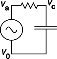
Figure 1: RC Circuit
Copyright © 2005 jsd
ABSTRACT: A lock-in amplifier has been constructed using the audio I/O system (“sound card”) on a Linux PC, plus a few thousand lines of software. This is not a simulation, but rather an implementation of a real lockin.
We discuss the operation of lock-in amplifiers in general, and the computer-based lockin in particular. This includes a review of what phasors are and how they are used.
See the instructions, warnings, and disclaimers in section 4.
Consider the RC lowpass filter circuit shown in figure 1. Suppose we want to know the amplitude and phase of the various voltages in the circuit. As a concrete example, suppose that under certain conditions we observe that the generator voltage (Va − V0) is 1.0 volt, the voltage drop across the resistor (Va − Vc) is more than 0.7 volts, and the voltage across the capacitor (Vc − V0) is also more than 0.7 volts ... all as measured by an ordinary voltmeter, with plenty of accuracy.
If you are wondering how 0.7 plus 0.7 can add up to 1.0, let me assure you that they do add up like that, under certain conditions of frequency et cetera. This is not a violation of Kirchhoff’s voltage law. The point is that the capacitor-voltage and the resistor-voltage are out of phase, and an ordinary voltmeter is not sensitive to phase.
The best way to understand this is in terms of phasor diagrams. The definition and fundamental properties of phasors are discussed in section 3.
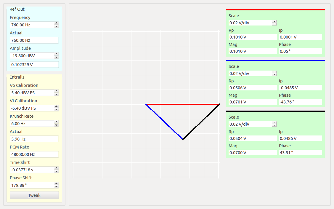
You can measure the amplitude and phase of a wave using a lock-in amplifier ... aka a lockin, aka a phase-sensitive detector. Figure 2 shows my lockin in actual operation.
The phasor representing the generator voltage (Va − V0) is plotted in red, while the phasor representing the capacitor voltage (Va − V0) is plotted in blue, and the phasor representing the resistor voltage (Va − Vc) is plotted in black. The horizontal axis measures the real part of the phasor, while the vertical axis measures the imaginary part.
It must be emphasized that this is real data, obtained by connecting my lockin to a real resistor and a real capacitor. It is not an “artist’s conception”. My lock-in amplifier is not a software simulation, but rather a real implementation using the hardware of a real PC plus some software.
The data is not quite perfect. The phase angles that are supposed to be 45 degrees are off by a degree or so. This is because the gain of my “sound card” inputs is not quite the same from channel to channel. It would be easy to correct for this, but sometimes it is nice to see real data, warts and all.
You can see that when plotted this way, the three voltages do add up, as they should. (Kirchhoff’s so-called “laws” are sometimes violated, but they are OK in this case.)
All the waves discussed here are sinusoidal. Only a single frequency component will be considered at a time.
You can ascertain the current in the circuit by looking at the resistor voltage. The voltage across the resistor is in phase with the current (at all frequencies), as required by Ohm’s law. For a sinusoidal wave, the voltage across the capacitor is 90 degrees out of phase with the current (at all frequencies), as expected in accordance with Q = CV, which essentially defines what we mean by capacitor. The generator voltage is 45 degrees out of phase with the current at this frequency; this angle will change as a function of frequency.
At high frequencies, the capacitor voltage is very small and is almost 90 degrees out of phase with the generator voltage. At low frequencies, the capacitor voltage is equal to the generator voltage, and almost in phase with it. At all frequencies, the capacitor voltage lags the generator voltage. In general, as a function of frequency, the capacitor voltage maps out a semicircle in the phasor plane. This should be obvious from the geometry of the situation, namely the right angle between the capacitor voltage (blue) and the resistor voltage (black). You presumably proved in high-school geometry that a triangle inscribed in a semicircle is a right triangle. It is also easy to calculate algebraically.
A lock-in amplifier with a slow low-pass filter on the output can be considered a type of narrow-band receiver. That is, it detects signals in a tiny bandwidth around the reference frequency.
It is sometimes claimed that this is a “revolutionary” capability, but really it is not. Superheterodyne radio receivers have been in use since World War I, have been commercially available since the 1920s, and have been in very widespread use since the 1930s. The lockin was invented by Robert H. Dicke in 1961.
The heterodyne design is based on knowing what frequency you’re looking for. This feature is shared by lockins and superheterodyne radio receivers.
What sets the lockin apart is knowing the phase you’re looking for, not just the frequency. If you know the signal of interest is in the cosine phasor component, you can throw away the sine phasor component. This reduces the noise by a factor of two, which is often quite significant.
Block diagram goes here. Local oscillator. Reference-out. Internal reference. Mixer. Filter. Display.
The software can be downloaded via ./lockin.tgz and the individual files can be perused via ./lockin-0.1/.
The software is observed to compile without warnings on a standard Linux (Ubuntu) system. Details on required packages can be found in the INSTALL file.
Required hardware includes a standard PC and audio interface (aka “sound card”). External USB audio interfaces are allowed, not just internal sound cards.
There must be at least one audio output and at least one audio input. Mic-level inputs are more desirable because they are more sensitive than line-level inputs.
Some .ctl files are included, but you may well have create one customized for your particular hardware. See section 2.3.
A Linux-based lock-in amplifier was described in 2008 (reference 1). It is described as freeware, but the software does not appear to be readily available.
Another computer-based lockin has recently been developed (reference 2).
Many other PC-based lockins are available, but they are in a different category because they require specialized hardware and/or nonfree software libraries. Standalone instruments – not PC-based – are widely available, but not cheap.
Mixer configuration: We need to do recording and playback at the same time, so the mixer needs to be set up just right. Use alsamixer to adjust the settings. When you’ve got it right, save the settings to a file using alsactl -f file.ctl store C, where C is the card number. You can get the lockin to tell you what filename it is expecting by running lockin -h.
Change the amplitude and re-check. If there are signs of saturation, lower the amplitude and start over.
V-out calibration: Disconnect any loads from the output. Connect a voltmeter and nothing else. Fiddle with the Vo Calibration setting box until the meter reading matches what the Ref Out amplitude window says.
V-in calibration: The idea is to fiddle the Vi Calibration window until the indicated magnitude (on the lockin) matches the actual voltage at the input. This voltage may be too small to measure conveniently.
Tweak Button : Phase Shift and Time Shift Calibration:
Push the tweak button (or, better, use the Alt-T shortcut). The first time you do this, it will zero out the phase of analyzer #1. Then change the frequency and hit Alt-T again. This will adjust both the phase shift and time shift, based on a linear model of phase as a function of frequency.
Specifically, the tweaker keeps a record of the phase and frequency for the last ten times you have pushed the button. If all ten have the same frequency, it just tweaks the phase. Otherwise it does a linear least-squares fit to the data, to model the phase versus frequency relation. Even cheap audio interfaces nowadays seem to be quite phase-linear, so this technique works pretty well.
The rationale for this is that when multiplying one sinusoidal wave by another and integrating over an exact number of cycles, there is no aliasing. The integral of cos times cos is exactly 0.5, the integral of cos times sin is exactly zero, and the integral of cos(Mωt) times cos(Nωt) is zero, for all integral N≠M.
In particular, when the referenceIn signal is being used, it controls the reference oscillator, and then the reference oscillator is used for multiplying things. This is a much better technique than using the referenceIn signal directly, because it could have all kinds of noise, distortion, and other imperfections.
In the audio system:
See reference 3.
Instructions: The computer-based lockin is not suitable for measuring anything other than audio signals at ordinary audio levels or less.
Make sure there is no significant stored energy in anything you hook up, e.g. capacitors.
It may help to put a preamp between the raw signal and the computer. It may be more convenient to apply proper grounding, shielding, and overload protection to the preamp than to the computer itself.
Warning: If you hook up high-voltage signals to your computer, you could destroy the computer and create risks of personal injury or death.
Disclaimer: This is not highly polished software. Both the code and the documentation are in a pre-alpha (experimental) or alpha (evaluation) phase, intended for investigation by people who know what they are doing. There is NO WARRANTY and no claim of merchantability or fitness for any purpose.
Copyright © 2005 jsd