Tetrahedral Resistor Network with Broken Symmetry
John Denker
1 Statement of the Puzzle
Consider the circuit diagrammed in figure 1.
There are six resistors. Five of them are identical, but the sixth
one is different. Assume the difference is large enough to be readily
measurable with an ordinary ohmmeter.
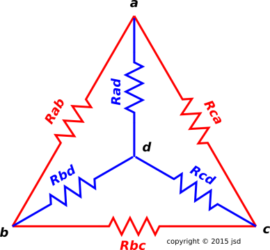 Figure 1
: Tetrahedral Resistor Network, Circuit Diagram
Here’s a puzzle for you: Figure out which of the resistors is the
oddball, by measuring the circuit using an ohmmeter. You must measure
the circuit as it is, without disassembling it.
Additionally, try to figure it out using the smallest number of
measurements. Also try to figure out the actual resistance of each
of the elments.
Note: You can make the problem dramatically easier by assuming that
the odd resistor always has less resistance than the others, perhaps
by building a completely symmetrical network and then adding something
in parallel to one of the elements. At this point the only nontrivial
bit is to figure out the value of R without doing a ton of work, which
requires a little bit of insight.
However, today we will solve the hard version of the problem, allowing
the odd resistor to be larger or smaller than the others.
2 Discussion
-
We note that the circuit has the symmetry of a
tetrahedron. If all the resistors were the same it would be a
regular tetrahedron, but since one of the resistors is different it
is a slightly irregular tetrahedron. The symmetry is discussed in
more detail in item 13.
-
Let the resistance of the normal resistors be r, and let the
resistance of the oddball resistor be x.
-
Notation: Rab is the physical resistor connecting
node a to node b. Meanwhile, Zab is the measured edge
resistance when we apply the ohmmeter to nodes a and b. It
includes contributions from the physical resistor plus all the stuff
in parallel with it.
-
Pick any resistor in the network, such as
Rab. Four of the other five resistors will be adjacent to this
one, by which we mean they connect to it at one end or the other.
The remaining resistor is located on the diametrically opposite edge
of the tetrahedron. In this case that is Rcd.
-
Terminology: The oddball resistor is sometimes called
the odd pole of the tetrahedron. The resistor diametrically
opposite the odd pole is the normal pole. The remaining four
resistors are said to be on the equator, halfway between the two
poles.
-
Note that if Rcd is the oddball, all the others
are normal, and by symmetry Rcd contributes nothing to the
measured resistance Zab, and in fact you can easily show that
independent of x. All you need for this are the basic formulas for
resistors in parallel and resistors in series.
-
It is equally true that if Rab is the oddball,
then the situation is once again symmetric, and Rcd contributes
nothing to the measured resistance Zab. You can easily show that
|
| |
Zop | | = | | x∥r | | (odd pole) | |
(2a)
|
|
| |
| | = | | | | | |
(2b)
|
| | |
|
| |
x | | = | | | | | |
(2c)
|
|
-
There will be four observed resistances on the
equator. By symmetry, these will all be equal. Qualitatively
speaking, the result will necessarily be somewhere in between the two
polar readings: the equatorial readings will not be as strongly
affected by the oddball as the odd polar reading, but they won’t be
completely immune like the normal polar reading.
Alas at this point the readings still don’t solve the problem,
because x could be larger or smaller than r. Knowing that the
equator is somewhere in between doesn’t tell us which pole is which.
-
With some thought you can convince yourself that the
equatorial reading is closer to the normal polar reading than
it is to the odd polar reading. This is because the effect of the
oddball is more diluted by the complicated series/parallel network.
You can check that this result is plausible by considering the
extreme cases x=0 and x=∞. If you want reliability, not
just plausibility, you have to do the math, as discussed in the next
item.
-
Calculating the exact value for the equatorial readings is a
chore, but it can be done. It helps to apply the wye-delta
transformation to the blue resistors in figure 1, to produce the equivalent circuit shown in
figure 2.
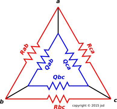 Figure 2
: After the Wye-Delta Transformation
In accordance with the usual formula, the resistances of the
delta-circuit elements are known in terms of the original wye-circuit
elements:
|
Qab | | = | | | Rad Rbd + Rbd Rcd + Rcd Rad |
|
| Rcd |
|
| (3)
|
And similarly for all cyclic permutations of (a,b,c).
What remains is a relatively simple series/parallel combination. We
can take it step by step. First we combine each red resistor with the
corresponding blue resistor:
Then we combine those in series/parallel:
The final observed impedance is:
-
All the results are shown in figure 3. The abscissa is the arctangent of
x, which allows us to scan from x=0 to x=∞ in a nice
systematic way.
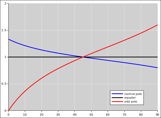 Figure 3
: Tetrahedral Resistor Network Readings
-
The three formulas can be put into a common form
as follows:
| | | | (normal pole) |
| | |
| | | | (equator) |
| | |
| | | | (odd pole) |
| (7)
|
-
Note the contrast:
|
Speaking of the physical resistors R: There are four
normals on the equator plus one more on the normal pole, for a
total of five normals. Finally there is the oddball on the opposite
pole.
|
|
Speaking of the measured resistances Z: There is a group of four
all the same, plus one higher, plus one lower.
|
Do not confuse the symmetry of the inputs with the symmetry of the
outputs. That is, do not confuse the symmetry of the structure with
the symmetry of the function.
3 Solution Procedure
3.1 Simple Version
This version requires four measurements in every case.
- Pick three edges that form a triangle. Measure them. You are
guaranteed that any such triangle will contain one polar edge and two
equatorial edges.
- You can identify the polar edge because it is different from the
other two. Measure the diametrically opposite edge, since that is
the other pole.
- Whichever pole has a reading closer to the equatorial readings
is the normal pole; the other one is the odd pole.
- You can determine the value of r from equation 1.
You can then determine the value of x from equation 2c.
3.2 Fancy Version
This version is optimized to use the minimum number of measurements.
Usually four measurements are required, but if you’re lucky you can
sometimes get by with three.
- Pick any two adjacent edges and measure the resistances.
- If they are the same, you have identified the equator. One pole
will bridge the V formed by these two edges (closing the triangle),
and the other pole will connect to the point of the V. Measure the
two poles.
- If the first two edges are not the same, select one of those
edges and measure the edge that is diametrically opposite. You now
have three measured edges that form a skew figure, not a triangle.
- There is a 50/50 chance that all three are different, in which case
the extreme values are the poles. This is the only case where you can
get by with three measurements. All other cases require four.
- If two are the same and one is different, the different one is
a pole. Measure the opposite pole.
- Whichever pole has a reading closer to the equatorial readings
is the normal pole; the other one is the odd pole.
- You can determine the value of r from equation 1.
You can then determine the value of x from equation 2c.
4 References
-
-
Donald Simanek,
“Challenging Physics Problems”
https://www.lhup.edu/~dsimanek/scenario/puzzles.htm