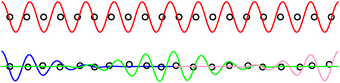
Figure 1: Delocalized and Localized Wavefunctions
The question was asked:
Why can the transmission of light (intensity) be greater through oil-soaked paper than through the same paper dry? Pioneer settlers in the midwest were said to use oil or lard-soaked paper sheets as windows; they shed rain and blocked the wind, while allowing light to pass through.
That’s a good one. Actually, let’s start by addressing the exact opposite question:
The most important thing is to understand why the un-oiled paper is white! Once you understand why the un-oiled paper is white, it will be much easier to understand why the oiled paper is translucent.
What is the definition of white? What is the physics of white? How do you make white? Why are clouds white? Why is the white screen in a movie theater proverbially called the Silver Screen?
Let’s start with something that isn’t white. A piece of pure crystalline quartz is highly transparent. It does not absorb light. It does have an index of refraction. A light beam will partially reflect off the air/quartz interface due to the index mismatch. If you take a zillion identical small quartz spheres and arrange them in a regular lattice like a crystal, you might think that all those little reflections would add up to make something quite non-transparent, but in fact a funny thing happens. If the lattice really is perfect, the scattering is coherent. The coherent forward scattering reconstructs the incoming wave perfectly, making the lattice transparent (although it has a refractive index of its own). Loosely speaking, you can visualize this in terms of the Huygens construction. For more on the role of microscopic scattering, see reference 1 and reference 2, or any solid-state physics text.
If, however, the lattice is not quite perfect, we don’t get perfectly coherent forward scattering. If the sample is large enough and/or imperfect enough, we get localization. If the little scatterers are situated on a perfect crystal-like lattice, but the scattering parameters (e.g. size) is variable from site to site, then we get Mott localization. If the sizes are uniform but the locations are randomized, we get Anderson localization. The physics will be discussed in more detail below, in connection with figure 1, but here’s the basic idea: We still have some forward scattering, but it is no longer coherent. If you try to do a Huygens construction but randomize the phases of N contributions, the total goes to zero as N becomes large. (This is a standard result for waves, and for vectors generally: Given a large number of vectors with random orientation, they add up to zero.) More quantitatively, the forward wave is exponentially attenuated with a length scale that depends on the amount of random scattering.
So what happens to all the light that can’t go forward, and can’t be absorbed? It rattles around for a while and then gets tossed out the front surface of our lattice of scatterers. The outgoing light has a wide distribution of angles. Our lattice looks white.
We can understand the microscopic situation with the help of figure 1. In the top half of the figure, we have a perfect regular lattice. A typical wavefunction extends all the way from the front of the material to the back of the material. We can couple to this wave function at the front and at the back.
In contrast, in the bottom of figure 1, we have an irregular lattice. Three more-or-less representative wavefunctions are shown. The blue wavefunction couples to the front of the material, but does not extend very far back; it does not couple to the back. Meanwhile, the magenta wavefunction couples just fine to the back of the material, but does not extend very far forward; it does not couple to the front. The green wavefunction is a “trap” state, deep inside the material, and does not couple to the front or the back. It may not be obvious from the diagram, but all three of these wavefunctions are orthogonal to each other, so they don’t couple to each other.
For more details on all this, see reference 3.
It should be emphasized that the individual fibers in a piece of paper are not white. They are beautifully transparent. It is only a moderately thick collection of randomly-arranged fibers that is white.
Note that you cannot make paper (or paint) that is really thin and really white. It’s physically impossible.
We are now in a position answer the original questions about pioneer windows:
You don’t get perfect transparency for various reasons: (1) Typical oil isn’t a perfect match for cellulose. (2) Typical paper contains not just cellulose but other junk. If you match to one, you can’t match to the other. (3) What’s worse is that the cellulose fibers are hollow and it is nearly impossible to get oil into the cores. Therefore there will always be some scattering off the cores. If we could lay hands on some paper made of randomly-arranged solid fibers (such as rayon, which is solid cellulose), I predict the oil-spot effect would be really spectacular.
In section 1, perfect crystals were mentioned as one way to achieve transparency.
That’s true as far as it goes, but not the whole story, because it doesn’t explain why noncrystalline substances – such as liquids, gasses, and glasses – are sometimes highly transparent.
Not all glass is transparent. As a familiar counterexample, Corelle™ dishes are made of glass, but are quite opaque.
As before, we need to understand transparency before we attempt to understand non-transparency.
As before, we can understand transparency in terms of coherent forward scattering. A crystal is one way to achieve this, but not the only way. The crucial requirement is that each small region of space have the same scattering amplitude and the same scattering phase shift. Roughly speaking, that means the substance must have the same index of refraction in each small region. (By "small region" we mean a region comparable in size to the wavelength of the light we are using.)
All glass is non-uniform at the atomic level. However, for transparent glass, this does not greatly affect the index of refraction when averaged over a wavelength-sized region. There are many, many atoms in such a region.
The best glass is phenomenally transparent. The glass used in undersea optical fibers loses only a few dB in thousands of kilometers.
Glass that has not been optimized for transparency will exhibit localization on the scale of meters or even less, due to region-to-region fluctuations in the index of refraction.
Liquids achieve transparency the same way glasses do. The structure is random on the atomic scale, but in a transparent liquid this does not greatly affect the index of refraction when averaged over wavelength-sized regions. In contrast, if there is a nonuniform index, such as in an emulsion of oil in water, the liquid will be highly non-transparent.
The air in the atmosphere is almost transparent, but not quite. Scattering by fluctuations in density (i.e. fluctuations in index of refraction) explains why the clear blue sky is blue, as discussed in reference 4.
This business about localization can be applied to electron wavefunctions as well as to light waves. This is the key to understanding how/why a real practical insulator is totally different from the hogwash explanation (large-gap semiconductor) given in almost all solid-state physics books. A large-gap semiconductor such as diamond is all-too-often called an insulator, but really it should be called merely a semi-non-conductor, since it cannot be used as a practical insulator. It will not immobilize any charge injected onto or into it. If you really want a practical insulator , you need localization of the electron wavefunction.
Physically, an undoped semiconductor is like a vacuum. The theory of this is discussed in reference 2 and especially reference 5.
If you inject some charge into a vacuum, it looks like an excellent conductor. In the absence of injected charge, it looks like an insulator. If you try to measure “the” conductivity of a given semiconductor, the results will vary over many many orders of magnitude, depending on whether there is a source of free charge. With semiconductors (as with so many other things in life) it is better to describe what they are doing, rather than to categorize what they “are”. It is not helpful to say semiconductors “are” conductors or “are” insulators. Instead, it is better to recognize that a given semiconductor might be conducting (at the moment) or might be insulating (at the moment).
In some tightly controlled applications, such as within an integrated circuit chip, it is possible to make conductors out of semiconductors, and to make insulators out of semiconductors (or out of the boundaries between semiconductors). In other applications, such as insulating a household extension cord, semiconductors would be quite unsuitable.
The relevant parameter is the size of the band gap, divided by kT. This means you can do the experiment in an undergraduate physics lab: Silicon at liquid nitrogen temperature has essentially the same physics as diamond at room temperature.
The size of the gap (relative to kT) is relevant if you’re trying to build a minority-carrier device, such as a bipolar junction transistor, but it is quite irrelevant for majority-carrier devices such as field-effect transistors. I’ve built FET circuits that work just fine at cryogenic temperatures. The fact that the band gap was huuuge compared to kT did not turn the device into an insulator.
Whether you have an efficient means for injecting charge depends on details. A sharp point is known to be good for injecting charge into a vacuum with very modest driving voltage. This is called field emission. (In air as opposed to vacuum, the same geometry produces corona, with almost but not quite the same physics.) Every VLSI chip has multi-millions of ohmic contacts. Making them is a bit of a black art, but I conjecture that the physics is roughly analogous to a field-emission point.
Practical insulators contain traps which immobilize injected charge.
In section 1 we learned that it is impossible to make something very white and very thin.
Interestingly enough, it is equally impossible to make something very black and very thin.
The simplest way to make a good (but not thin) absorber is to choose a material where the refractive index has an imaginary part that is slightly greater than zero. In such a material, there will be gradual exponential decay of the amplitude of any propagating wave. So far so good.
You might think we can make the thing thinner if we give the index a larger imaginary part. That works up to a point, but there’s a problem.
Suppose the refractive index has enormous imaginary part. If you have a wave incident on such a slab, the wavefunction inside the slab must have zero amplitude. Now consider the boundary between free space and the slab. The only way to satisfy the wave equation is to have 100% reflection. The index mismatch causes a reflection.
You can get rid of the reflection using an antireflection coating ... but to be effective the coating cannot be thin compared to the wavelength of the incident light.
Strictly speaking, the Huygens construction in its original form cannot possibly be correct. We know this because the wave equation is a second-order differential equation, and therefore requires two boundary conditions ... whereas Huygens supplies only one.
Physically, this is well illustrated by the class single-slit diffraction experiment. The physics is different depending on whether you have a slit in a black barrier or a slit in a reflecting barrier ... but the Huygens prediction is the same in either case.
It is possible to fix this problem using a somewhat more elaborate construction, as discussed in reference 6.
The Liénard-Wiechert potentials are somewhat similar in spirit to the Huygens construction, and are rigorously correct. See reference 7.