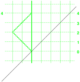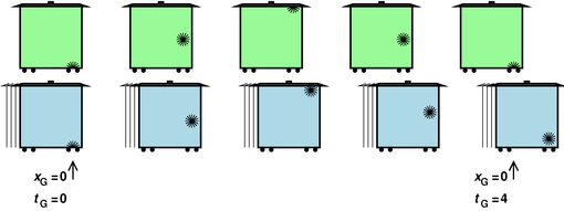
Figure 1: Trains Carrying Light Clocks
Our task for today is to understand the behavior of clocks that use the travel-time of a light pulse as their fundamental timekeeping mechanism. We have two such clocks, each moving relative to the other, so this becomes an exercise in special relativity.
There are two types of light clocks, the basic type considered in this section, and the transverse type considered in section 2. The basic situation is shown in figure 1.
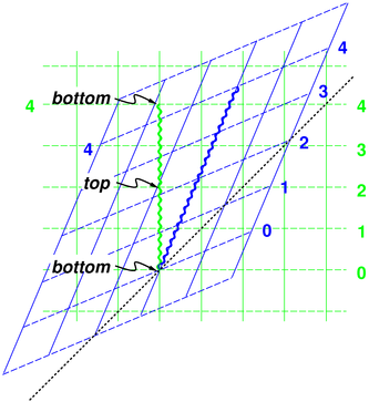
The green train car is stationary in the lab frame. It is parked so that the “front” of the car is at position xG=0. At time tG=0, a flash of light is emitted from the front of the car. The light travels to the back of the car, is reflected, and is received at the front of the car some time later. The length of the car is two units, so the round-trip travel time is four units, as shown in the spacetime diagram in figure 2. The worldline of the light pulse is shown by the green wavy line.
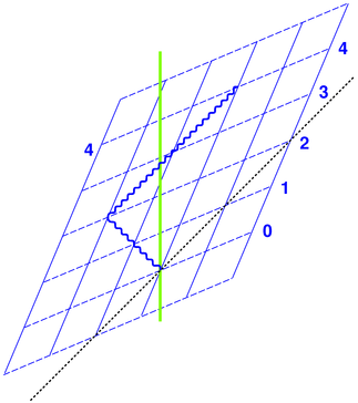
The situation is the same for the blue car. The two cars were built to the same specifications, and are identical in every way except for the color ... and except for the fact that the blue car is moving relative to the green car. This is uniform straight-line motion. In accordance with Galileo’s principle of relativity, observers comoving with the blue car don’t care about any such motion. Their analysis of what happens within the blue car is utterly straightforward. The length of the car is two units, so the round-trip travel time is four units, as shown in figure 3. The worldline of the light pulse is shown by the blue wavy line.
Note: If you want to make your own spacetime diagrams, you may find it convenient to start with prefabricated spacetime graph paper. Then all you have to do is add the events. You can print your own spacetime graph paper from the files in reference 1.
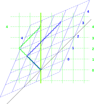
We have chosen coordinate systems so that (tG,xG) = (0,0) in the green frame represents the same spacetime event as (tB,xB) = (0,0) in the blue frame. This makes it easy to compare the two clocks, as in figure 4.
The end of the blue wavy line occurs at blue time tB=4, as it should. We see that according to the green frame, this occurs “late” i.e. later than green time tG=4. This is the origin of the highly problematic notion of “time dilation” i.e. the notion that “moving clocks run slow”. Actually the situation is completely symmetrical; according to blue observers, the end of the green wavy line ends late, i.e. later than blue time tB=4, as you can easily verify by looking at figure 4.
By way of analogy: when you look at a ruler almost end-on, we do not say that “the” length of the ruler is shortened; instead we say that the projection of the ruler is shorter than its intrinsic length.
So it is with clocks. Rather than saying “moving clocks run slow”, the modern (post-1908) approach is to say that each clock keeps perfect time in its own reference frame. It is only the projection of each reference frame onto the other that is affected. This is discussed in greater detail in reference 2.
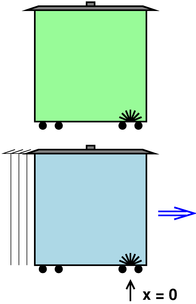
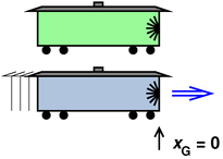
Figure 5 shows the same situation as figure 1, except that the light pulse travels vertically, i.e. transverse to the relative motion of the cars. Also the box cars are much boxier and taller, so the round-trip time will be conveniently the same as before.
Figure 6 shows the situation in more detail, step by step, in a series of five snapshots. You can see that relative to the blue reference frame, the blue light moves strictly vertically ... whereas relative to the green reference frame, the blue light has a horizontal component to its motion, as you can see from the fact that it starts out at xG=0 but ends up well to the right of xG=0.
You can also see that according to the green observers, the blue light appears to arrive late. It will arrive at the bottom of the car later than time tG=4. One goal of this section is to understand and quantify this lateness.
The analysis is shown in figure 7. The green clock is very easy to analyze. As before, the spacetime diagram shows the x and t dimensions. The tricky bit is that the light is traveling in the y dimension, which is not shown, so you have to use your imagination to see the light moving up (out of the paper) during the first two units of time, and then moving back down during the next two units of time. The entire round trip takes 4 units of time, as shown by the green wavy line.
The same words apply to the blue clock. It is very easy to analyze in the blue frame of reference. According to the blue observers, the light takes 4 units of time to make the round trip.
So far we haven’t done anything exciting. The spacetime diagrams practically draw themselves.
The most interesting thing we can do at this point is to see what happens when we impose the requirement that the speed of light must be the same in all frames. (This requirement was so obviously satisfied in figure 4 that it wasn’t worth discussing.)
This requirement is trivially satisfied when the green observers check the green clock, and when the blue observers check the blue clock, but things get interesting when the green observers check the blue clock (or vice versa).
Let’s consider just the first half of the round trip, i.e. the part where the light travels from the floor to the ceiling of the blue train car. Let this distance be denoted by H. In our diagrams, H=2, but in the interest of elegance and generality let’s call it H. According to the green observers, the blue light travels a distance D. This D is greater than H, because while it is moving a distance H vertically it is also moving a distance vt horizonally. Here v is the relative velocity between the two frames of reference, and t is the amount of time – in the green reference frame – needed for light to travel the whole distance D. We don’t yet know t and we don’t yet know D, but we can work out what we need to know using a little algebra.
Pythagoras tells us the total distance is:
| D2 = H2 + v2 t2 (1) |
We don’t need to worry about any sort of FitzGerald-Lorentz contraction of H, because it is transverse to the motion. Just as a rotation in the xy plane leaves vectors in the z direction unchanged, a rotation in the xt plane (i.e. a boost in the x direction) leaves vectors in the y direction unchanged.
Now we invoke the postulate that says the speed of light is the same in all reference frames, so therefore
| (2) |
Let’s pay attention to the physics for a moment. The physics we are measuring is the time between two spacetime events, namely two ticks of the blue clock. If we measure this time in the blue frame, i.e. the frame comoving with the blue clock, it is called the proper time and is denoted τ (“tau”). Proper time is high on the list of things we expect to have physical significance. The same two events, when projected onto the green frame of reference, are separated by a time we’ve been calling t. This t implicitly depends on the velocity v. In the special case where v=0 we have t equal to τ.
We can exploit this special case by setting v=0 in the previous equation. This allows us to connect H to τ:
| (3) |
and plugging that back into the previous equation we see
| (4) |
and a little rearrangement results in
| (5) |
or
| (6) |
This is a famous result, and tells us quantitatively how “late” each frame’s clock appears when projected onto the other frame’s axes.
There are much, much easier ways of obtaining this result. For example, a glance at the rotation matrix
| ⎡ ⎢ ⎣ |
| ⎤ ⎥ ⎦ | (7) |
(as found in reference 3 and elsewhere) tells you that each frame’s clock will appear late by a factor of cosh(ρ) when projected onto the other frame’s axes. Here ρ is the rapidity, and v/c = tanh(ρ). Then equation 5 is nothing more than the trigonometric identity:
| cosh2 = |
| (8) |
The easy way to understand relativity is to see it as nothing more than the geometry and trigonometry of spacetime, as discussed in reference 3.
In contrast, the hard way to derive special relativity is by grinding out a series of Gedankenexperiments (such as the light clocks considered here). It must be emphasized that the “time dilation” factor considered here is far from being a complete description of relativity. If you insist on taking the non-spacetime approach, i.e. the pre-1908 approach, you need (at the very least) time dilation, length contraction, and breakdown of simultaneity at a distance. (You’re really much better off using modern ideas such as undilated proper time, uncontracted proper length, four-vectors, and spacetime diagrams.)
In any case it is nice to know that the physics of light clocks is consistent with the trigonometry of spacetime as set forth in reference 3.
Note that in figure 6, the light in both cars is emitted at xG=0. The question sometimes arises, “Why does the light in the blue car not remain at position xG=0 and simply change its (y,t) values? That is, when viewed in the lab frame, why does the blue light partake of the blue car’s left-to-right motion?”
Short answer: Because we engineered it to do that. We engineered the blue light source to aim upward along a contour of constant xB=0.
By the same token, the green light source is engineered to aim upward along a contour of constant xG=0. Remember, the two cars are built to the same specifications.
More detailed answer: There has to be some apparatus in each car to aim the light, perhaps:
If the apparatus is moving, its aim-point will be moving.
Draw the spacetime diagram for an omnidirectional source plus a pinhole. You will see that it selects whatever fraction of the light is moving in the correct direction, and discards the rest.
Here’s a nice one-line proof of the proposition “if the apparatus is moving, its aim point must be moving”: Otherwise it would violate Galileo’s principle of relativity.
By the way: it is important to realize that the blue car has been moving all along at a steady rate. (You will get the wrong answer if you imagine that the blue car was stationary at t=0, emitted the pulse of light, and then started moving.)