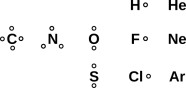
Figure 1: A Few Small Molecules
| How to Draw Molecules ... |
| Just Like Lewis Dot Diagrams, Only Easier & Better |
Our primary goal for today is to be able to draw diagrams of molecules, such as we see in figure 1.
These diagrams tell us that the F2 molecule has a single bond, the CO2 molecule has two double bonds, and the HCN molecule has one single bond plus one triple bond.
There are two main methods for constructing such diagrams.
Part I is meant to give a “clean” and self-contained explanation of BABE and of hole-counting. That means it is suitable for readers who have never heard of Lewis dot structures.
In this section, we discuss a way of diagramming molecules that has many advantages. It is in all ways preferable to Lewis dot diagrams.
The diagrams provide predictions about the number of bonds. This is important, because it implies, among other things, predictions about the existence, non-existence, and reactivity of molecules. That is, when we learn there are four single bonds in CH4 and two double bonds in CO2, we also learn that reactions that produce molecules of CH4 are vastly more plausible than reactions that produce molecules of CH2, and similarly molecules of CO2 are more plausible than molecules of CO4.
Our first goal is to draw (and understand!) some simple molecules. Before we start talking about rules, let alone theories, let’s look at some data.
| N≡N | triple bond | 5 electrons in the N=2 shell | ||
| O÷O | two units of bond strength | 6 electrons in the N=2 shell | ||
| F−F | single bond | 7 electrons in the N=2 shell | ||
| Ne Ne | essentially no bond1 | 8 electrons in the N=2 shell |
The trend is clear: In this part of the periodic table, more electrons means less bonding. We shall see that this trend holds true for a broad class of interesting and important molecules (but not for all molecules).
We can construct a simple rule for drawing such molecules and predicting the number of bonds. We will begin by stating the rule and applying it to some examples, and then in section 2.2 we will explain the rationale behind the rule.
The procedure begins with figure 2, which can be considered a fragment of a simplified periodic table. Hydrogen is shown with one dot, representing one hole, because it is one electron shy of the helium closed-shell configuration. Similarly fluorine has one hole, because it is one electron shy of neon.
This is just the venerable idea of valence, with the twist that the dots represent hole-valence, not electron-valence. The elements in figure 2 all have the property of being “electron rich” which means they have relatively few holes.
This meaning of the word “hole” has been in use for many decades. You may have encountered it in connection with P-type semiconductors. It is pretty much synonymous with “vacancy”. It means nothing more or less than a place where an electron could have been, but is not. In particular, holes could perfectly well be high-lying vacancies, not just low-lying vacancies. (This stands in contrast to ordinary back-yard holes, which always extend downward, below the general terrain.)
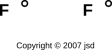
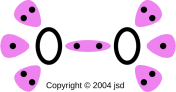
We can use the fluorine molecule as our first example. To diagram the F2 molecule, we start by drawing the atoms. Figure 3 shows two independent fluorine atoms. Each carries one hole, as we know from figure 2.
We are free to slide the holes around. Figure 4 shows the same thing, with the holes rearranged to face each other.
Finally, we connect the dots. Two holes make one chemical bond, as shown in figure 5.
Unlike a Lewis dot diagram, this figure does not portray electrons, but rather holes. (The notion of holes has been part of physics since 1930, as discussed in section 10.1.) That is, each little dot in the diagram represents the absence of an electron from an antibonding orbital.
Notice the logic here: In electron-rich molecules, what we casually call “bonding” might more logically be called absence of antibonding. It’s a double negative.
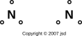
As our next example, we turn to nitrogen. The procedure is the same. To diagram the N2 molecule, we start by drawing the atoms. Figure 6 shows two independent nitrogen atoms. Each carries three holes, as we know from figure 2.
Next, we slide the holes around so that they face each other. Finally, we connect the dots. Two holes make one chemical bond. The nitrogen molecule contains a triple bond, as shown in figure 7.
Figure 7 is the normal, conventional way of diagramming the N2 molecule. Meanwhile, figure 8 shows the same thing with a little extra detail. It shows three antibonding orbitals (in color) each of which bears two holes.
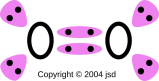
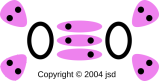
Let’s consider oxygen, which is a slightly tricky case. If you blindly follow the simplified procedure outlined above, you will wind up with a double bond. That is, the molecule will be diagrammed as O=O.
However, we are allowed to use additional information.
For any (or all!) of those reasons, we can conclude that oxygen contains unpaired electrons. Therefore diagramming the molecule as O÷O is vastly preferable to O=O. The preferred diagram is also shown in figure 9.
Figure 9 shows the O2 molecule with a moderate level of detail. Meanwhile, figure 10 shows the same thing with a little extra detail. It is useful to compare this against figure 8. In both cases we have three antibonding orbitals. The difference is that in nitrogen, the orbitals are fully populated, for a total of three units of bond strength, while in oxygen, there is only fully-populated orbital and two half-populated orbitals, for a total of two units of bond strength.
To repeat: hole-counting alone does not suffice to tell us whether O÷O or O=O is the preferred representation of the oxygen molecule. We need additional evidence from observation and/or theory to tell us that O÷O is the right answer. This is discussed more fully in section 2.4.
To arrive at the most appropriate structure, a good rule of thumb is to distribute the bonds so as to minimize formal charge. This tends to minimize the electrostatic potential energy, which is an energetically favorable thing to do, other things being equal.2
The procedure is to break each bond apart into two holes. (That is, break each dash into two dots.) For the bond between atom A and atom B, assign one of the dots to each atom. Then compare the number of dots assigned this way to the number of dots the atom “normally” has, where normal is defined by the table in figure 2. If the assignments are the same, the atom has zero formal charge. If the atom has more holes than normal, it bears a positive formal charge, and if it has fewer holes than normal, it bears a negative formal charge. Remember, these dots represent holes, not electrons, and each hole makes a positive contribution to the formal charge.
The idea of assigning half of each bond to each of the atoms makes perfect sense for symmetrical molecules, but is only a first approximation in non-symmetrical molecules. It is certainly not a law of nature.
Applying this rule gives us:
| (1) |
It is certainly possible to imagine something like H−O=C=N, but it would be disfavored due to needlessly high electrostatic potential energy. It would have positive formal charge on the oxygen, and negative formal charge on the nitrogen ... unlike the formulas in equation 1, which have zero formal charge on each of the atoms.
It is amusing to note that both of these acids have the same conjugate base, namely the cyanate ion:
| (2) |
The symbol to the right of the O in equation 2 is not a dash; it is a superscript minus sign. I know a minus sign looks a lot like a dash, but in this case it is a minus sign. You can recognize it as such partly because it is up in the exponent, and partly because it does not join two atoms.
You could imagine something like O=C=N((−)) (which could be called the isocyanate ion), but since oxygen is more electronegative than nitrogen, it makes sense to put the negative charge on the oxygen.
Note: Electrons are very much more mobile than protons. The isocyanate ion would convert immediately to the cyanate ion. In contrast, unionized isocyanic acid converts slowly, if at all, to cyanic acid.
Let’s move on to a larger and more complicated molecule, namely acetic acid. The first step, as always, is to figure out what molecule we’re talking about. In this case its systematic name is ethanoic acid, and its formula may be written CH3COOH.
The easiest way to proceed is to draw the molecule, placing next to each atom one dot for each hole that it contributes – counting down from the appropriate atomic closed-shell configuration – as indicated in figure 2. Therefore the acetic acid molecule looks like
        H    O
        .   ..

        .   ..
    H. .C. .C
        .   .

        .    .
        H    O. .H
Then we just connect the dots. Observation tells us this molecule is non-paramagnetic, so the simple rule “two dots make a dash” is all we need. The result is:
        H    O
        |   //
    H - C - C
        |   \
        H    O - H
Each dash represents one bond. For electron-rich molecules such as this, each bond is due to holes (i.e. the absence of electrons) in a high-lying antibonding orbital.
With a little experience, you discover that it is possible to save some work by treating the methyl functional group as a black box, like this:
             O
            //
    (CH ) - C
       3    \
             O - H
or equivalently
             O
            //
       Me - C
            \
             O - H
It is also interesting to see what happens when the acetic acid molecule reacts with water. In the classical approximation, the result can be drawn as:
             O
            //                (+)
       Me - C              H - O - H
            \ ((-))            |
             O                 H

        Acetate            Hydronium
          Ion                 Ion
We see that on the acetate ion, there is an oxygen with a formal negative charge, and only one hole associated with it, while on the hydronium ion, there is an oxygen with a formal positive charge, and three holes associated with it.
In this diagram, the formal charges are indicated in double parentheses, because they don’t tell you anything you don’t already know. If the indications were missing, you could easily reconstruct them based on the valence of each atom and the number of bonds it has.
The rest of this subsection is tangential to our main discussion, but it has tremendous practical ramifications, so we’d better mention it: In the classical approximation there are two different ways of drawing the acetate ion, namely(-) O O / // Me - C <--> Me - C \\ \ (-) O OEither one of the oxygens could get the double bond, while the other one gets the formal negative charge. Actually neither of these alternatives is really correct, for the same reason that neither of the Kekulé structures correctly describes benzene. In fact you get a quantum-mechanical resonance. That is, the superposition of the two alternatives has a lower energy than either of them separately. The process of resonance involves moving an electron from one oxygen to the other. This only works in the ion. In contrast, in the neutral acid molecule, there are two alternatives, but the rate of quantum-mechanical tunneling from one to the other is negligibly small, since it would require moving a proton, not just an electron. This is important, because it means the ion’s energy is resonantly lowered while the neutral molecule’s energy is not lowered. This makes the acid much stronger than it would otherwise be, by making it energetically favorable for the acid to get rid of its proton.
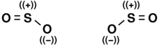
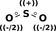
Now let’s examine sulfur dioxide. As usual, the starting point is to draw the atoms with the right number of dots, i.e. the right number of holes. This gives us a rough idea of what’s going on, as shown in figure 11.
Next, as usual, we see if we can combine the dots into bonds, to create a ball-and-stick model of the molecule. The two possibilities are shown in figure 12.
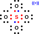
The final answer will be some sort of resonance i.e. a quantum mechanical superposition of the two ball-and-stick models. This is shown in figure 13.
If you want to attribute half a unit of negative formal charge to each oxygen atom, and a full unit of positive charge to the sulfur atom, that is not necessary but is harmless provided you don’t take it too literally. There is no well-defined dividing line that determines which part of the electron cloud “belongs” to one atom or another.
In any case we know from experiment that the SO2 molecule is bent and has a nonzero electric dipole moment. (Contrast this with CO2 which is linear and has no dipole moment.)
Also, spectroscopy and molecular orbital calculations tell us that the 3d orbitals make no observable contribution to the bonding in SO2.
As always, diagrams of the sort we are constructing here describe covalent bonding. A bond between dissimilar atoms will exhibit some percentage of ionic character. A single bond between sulfur and oxygen should have roughly 22% ionic character.
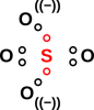
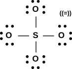
Another example that illustrates the simplicity and power of the hole-bonding approach is the sulfate ion, SO4=. As usual, we start by drawing the atoms, with the correct number of dots, where each dot represents a hole in an antibonding orbital. We started with ten dots, because each of the five atoms is divalent according to figure 2, but we erased two of the dots because of the double negative charge carried by the ion. Remember the dots represent holes, and the two negative charges fill those holes.
We then replace pairs of dots with dashes representing a two-hole bond. The diagram practically draws itself. The molecule is tetrahedral and completely symmetric:
If you want to think of this as having a +2 charge on the central sulfur atom, and a −1 charge on each of the four oxygens, that’s optional but harmless. That is consistent with basic electronegativity ideas, and semi-quantitatively consistent with the electron-density data from detailed quantum chemistry calculations.
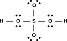
There is no trouble drawing a sensible diagram for the sulfuric acid molecule, as shown in figure 16.
This stands in contrast to the usual Lewis dot approach, which has some problems, as discussed in section 7.3.
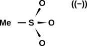
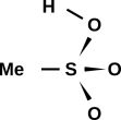
A diagram of the methanesulfonate ion is shown in figure 17. In the ion, all three oxygens are equivalent. In contrast, in the methanesulfonic acid molecule, as shown in figure 18, the acid hydrogen breaks this symmetry.
When we check the formal charge, we find a formal charge of +2 on the sulfur atom, and a formal charge of −1 on each of the three oxygen atoms in the methanesulfonate ion. This is consistent with the overall charge (−1) on the ion. This is also consistent with what we know about electronegativity; oxygen is considerably more electronegative than sulfur.
Similarly in the acid molecule, we find a formal charge of +2 on the sulfur atom, zero formal charge on the acid oxygen, and a formal charge of −1 on the other two oxygens. Again this is consistent with the overall charge balance, and consistent with what we know about electronegativity.
For a discussion of how our diagrams differ from the prior art, see section 7.4.
It must be emphasized that the minus sign in double parentheses in figure 17 is strictly parenthetical; you could erase it and the diagram would have the same meaning. You can verify and/or reconstruct the parenthetical minus sign by adding up the formal charge on each atom in the drawing. It would be quite wrong to calculate the formal charge according to the drawing and then add the parenthetical charge; that would be counting the same charge twice.
Such a parenthetical charge indication stands in contrast to a formula such as H−, which is an ion, unlike H which is a neutral atom. The minus sign in the H− formula is not parenthetical. Similarly OCN− is an empirical formula, and the minus sign is necessary to indicate its charge, in contrast to N≡C−O which is a structural diagram, and the charge can be inferred from the structure, namely N≡C−O((−)).
| In mathematics, parentheses are used for grouping, with no implication that the contents are merely parenthetical. | In written English, parentheses are used for parenthetical remarks. |
I use double parentheses when I want to make it clear that something is parenthetical, not a grouping.
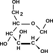
Figure 19 shows a sketch of a molecule with a fair bit of biological significance, namely glucose.
To sketch this, you need not only the empirical formula, but also some clue about which isomer is desired. The isomer shown here is quite common in nature. This figure is meant to show the number of bonds and the topology (i.e. what is connected to what); it is not meant to show every detail of the three-dimensional shape.
Most biomolecules are sufficiently electron-rich that the simplest hole-counting notions suffice.
Figure 19 is what you get by using the hole-counting method. It is consistent with the way professional biologists and biochemists sketch this molecule. If you doubt this, go to http://www.google.com/search?q=glucose and look at the results.
We are quite aware that hole-counting is not the only way of predicting the topology and the number of bonds. There is another method that is almost universally taught in high-school chemistry textbooks ... but it is not consistent with the known facts about molecules, and is not consistent with the way professionals draw things. This is discussed in Part II.
To summarize this section:
If you are ever tempted to violate this rule, it may mean that other rules are being violated as well. Double-check that the compound really is electron-rich, and double-check the rules about formal charge.
Hole-bonding diagrams correctly predict the number of bonds in every case where Lewis dot diagrams had any hope of making correct predictions ... and they have the advantage that they can be extended to additional cases, plus the advantage of being consistent with the paramagnetism data, the spectroscopic data, et cetera.
At the simplest level, we can explain the hole-bonding method by saying there is abundant observational and theoretical evidence that antibonding orbitals exist.
If somebody asks what, exactly, is the evidence, we can either tell them, or (if necessary) say that the full details are beyond the scope of the course.
If you want a mental picture that folks can use to make the antibonding idea more concrete, you can model each antibonding orbital as being a spring in compression, trying to destroy the molecule by pushing the atoms apart. In particular, it behaves like an air-spring, i.e. a parcel of gas under pressure, pushing the atoms apart. Each bond that we draw represents a net attraction, because it portrays the absence of a repulsive force.
For a truly introductory treatment, stop here!
To a more-sophisticated audience, I would point out that the air-spring analogy is really rather good. The pressure of the gas comes from the kinetic energy of the particles ... as does, ultimately, the repulsive force of the antibonding orbitals.
If people can accept that the sun’s size is determined by a tradeoff between an attractive interaction (gravitational PE) and an outward pressure (due to the KE of the particles), they ought to be able to tolerate the idea that atoms also make a tradeoff between an attractive interaction (electrostatic PE) and an outward pressure (KE again).
At the next level of detail, I remark that because of degeneracy, electrons produce a greater amount of pressure than you would have expected based on a naïve classical model. That is, an atom is more like a neutron star than like the sun, as discussed in reference 1.
Also at the not-quite-introductory level, I would point out that compared to F2, O2 has fewer electrons but more bonding. The same remark applies at every step in the sequence Ne2 → F2 → O2 → N2, in the sense that progressively fewer electrons means progressively more bonding. The number of bonds is observable in terms of the nonexistence of Ne2 and the progressively increasing binding energy in the rest of the sequence. This is direct evidence in support of the antibonding idea: we see progressively fewer electrons and progressively more bond-strength. So ... this basic reactivity data provides evidence in support of the hole-bonding idea. What could be more appropriate than that? It’s not necessary to make it more complicated than that.
At the next level of detail, I would point to the spectroscopic data, which has been around for over 100 years, as strikingly direct evidence for molecular orbitals.
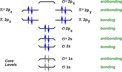
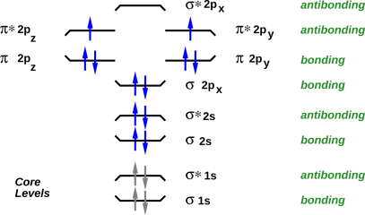
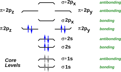
A good way to visualize the orbitals, and the filling of orbitals, is to draw energy level diagrams such as figure 20 through figure 23. If you want more information about what these diagrams mean, see e.g. reference 2.
In all such diagrams, energy increases vertically. The energy is not shown to scale, but the ordering of the levels is shown correctly. The electrons in the core levels are shown in gray, because they almost never participate in chemical reactions.
The bonding versus antibonding character of each level is encode three ways in the diagram: The tips of the level turn up for bonding levels, and turn down for antibonding orbitals. The name of the level has a “*” in it for antibonding orbitals, and not for bonding orbitals. Finally, off to the right, the levels are explicitly labeled “antibonding” or “bonding”.
The name of each level tells us something about the symmetry of the molecular orbital wavefunction, and about how it can be derived from the atomic orbitals of the atoms that make up the molecule.
In all of these four cases, there are three high-lying antibonding orbitals.
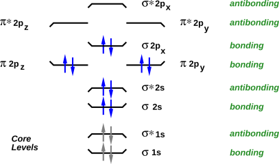
The naïve hole-counting procedure as described above is more-or-less mechanical and mindless. It correctly predicts the number of bonds in all situations where the Lewis fairy-tale had any hope of giving the right answer, namely in all situations where the molecule is sufficiently electron-rich that all its bonding orbitals are filled. (That means, among other things, that adding an electron to the molecule – for instance by replacing C with N, or replacing N with O – will reduce the net number of bonds by half a unit, by occupying an antibonding orbital.)
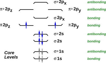
For molecules that are not so electron-rich, naïve counting doesn’t suffice. The Lewis approach has no hope of getting the right answer for such molecules, and cannot be repaired or extended. In pleasant contrast, the molecular-orbital description does of course get the right answer. The canonical illustration of non-naïve counting is dicarbon. The octet fairy-tale predicts that it should have a quadruple bond, but the real molecule has only a double bond. As we move along the series F−F, O÷O, N≡N, every time we remove two electrons we increase the number of bonds, by depopulating antibonding orbitals, as shown in figure 20 through figure 22. But when we extend the series, stepping from dinitrogen to dicarbon, we remove two electrons from a bonding orbital, as shown in figure 23. Therefore the number of bonds goes down to 2, not up to 4. If all we cared about was bond-strength, we would blissfully write C=C ... but that would give a misleading picture of the hole-count. In some cases, we need a picture that assigns the correct formal charge in dicarbon. In such cases, the preferred picture is C/=\C, where
The symbol C/=\C tells us we have a total of eight holes, i.e. four holes per carbon, i.e. a net neutral charge ... and a net bond strength of two.
To repeat: you can’t get the right answer for dicarbon just by naïve counting; you have to actually know something about the molecule. That is, you have to look at the energy levels of the molecular orbitals, as shown in figure 23. For more information, see e.g. reference 2.
Similarly, for very electron-poor molecules such as Li2, you are better off counting electrons than counting holes. We depict this differently, namely Li∼Li in which the curly ∼ symbol represents the presence of bonding electrons (counting up from helium) not the absence of antibonding electrons (counting down from neon).
Amusingly, dicarbon can be represented in two ways, either as C/≈\C (counting up from helium) or as C/=\C (counting down from neon):
As a separate issue, naïve counting does not suffice to predict that O÷O is a better description of the oxygen molecule than O=O. We start by considering both possibilities, and then use the available experimental and/or theoretical information to decide which version is better. One option is to observe that liquid oxygen is attracted by a magnet. (In contrast, liquid nitrogen shows no comparable attraction.) Alternatively, you don’t even need a magnet, and you don’t need a fancy spectrometer: If you put liquid oxygen and liquid nitrogen in transparent flasks, you can see from across the room that they are different. The oxygen has a pale blue color, due to the unpaired electrons. A third option is to look at the molecular orbital energy-level diagram, where you discover that there are two degenerate orbitals into which the highest-lying electrons can be placed. In accordance with Hund’s rule, the electrons will unpaired whenever there are enough energetically-accessible orbitals to make unpairing possible. All in all, we have multiple lines of evidence telling us that O÷O is vastly preferable to O=O.
Similar remarks apply to B2. A glance at figure 24 allows us to predict that it has one unit of bond strength, that it is paramagnetic (which it is), and that its spectrum shows a triplet Zeeman splitting of the ground state (which it does). To figure out what is going on in this molecule, it is easier to count electrons rather than holes, counting up from helium rather than counting down from neon (although counting down would give the right answer also). To depict this molecule in a way that shows the bonding as well as the antibonding, you can write B\;/B. Here we use a semicolon instead of a colon to indicate that we are counting electrons, not holes. Similarly we write the slanted lines the other way (i.e. \ / instead of / \) to indicate electrons not holes.
In general, if you observe that a molecule is paramagnetic, it tells something about the degeneracy of the highest molecular energy level, and conversely if you know the energy levels you can predict the paramagnetism. This is in stark contrast to the Lewis approach, which makes irreparably wrong predictions about O2, and cannot describe B2 at all.
Consider the contrast:
| Here’s the central unifying idea: In general, you need to think about the molecular orbitals. You need to figure out which bonding orbitals are occupied and which antibonding orbitals are occupied. | For electron-rich molecules, all the bonding orbitals are filled, so a simple mechanical hole-counting procedure suffices. Hole-counting is not fully general, but its domain of applicability covers a remarkably large number of molecules, including most of the molecules commonly encountered in organic chemistry. |
Some peculiar additional examples are discussed in section 5.
Aubau is the German word for “building up”.
The Aufbau principle has been known since the earliest days of quantum mechanics. It is a rule of thumb, not a rigorous theorem. Among other things, it tells us that when we go from O2 to F2, we expect the two molecules to have qualitatively similar energy-level diagrams, which is just what we see in figure 21 and figure 20. The main difference is that in F2, the levels are more fully occupied. Same levels, more occupation.
There are exceptions to the Aufbau principle. You can see that in going from N2 to O2, there is one pair of levels that re-order themselves. But the rest of the energy-level diagram is pretty much undisturbed.
It is worth noting that as we go from O÷O to F-F, the number of bonds decreases. F-F has more electrons but less bonding. That is consistent with the Aufbau principle, because we are not depopulating pre-existing bonding orbitals; we are populating a new antibonding orbital.
For more on this, see section 8.4.
It is important to know the shape of molecules. For instance, the well-known properties of water depend crucially on the fact that the molecule is bent, not linear in shape.
Lewis dot structures are often praised as being a stepping-stone toward VSEPR (Valence Shell Electron Pair Repulsion) which is a convenient method for predicting bond angles. Like Lewis dot diagrams, VSEPR is based on the unjustifiable idea of molecular octets, and an unjustifiable focus on bonding orbitals (to the neglect of antibonding orbitals).
The purpose of this section is to point out that approximate bond angles can be predicted without basing the prediction on “molecular octets”. This is the final nail in the coffin of “molecular octet” notions.
This will be presented as an empirical rule of thumb, without any deep derivations.
The ideas here in section 4 are much less well-founded than in other sections. When we say to use a wooden molecule of a carbon atom, pre-drilled with four holes in a tetrahedral pattern, you may reasonably ask “why” we should start there. The answer is that empirically and retrospectively, starting there leads to qualitatively-correct predictions in a goodly number of simple cases.
Disclaimer: Let’s be clear: The models presented here in section 4 are partly bogus and partly fortuitous.
You shouldn’t stake your life on any predictions made by such models … but let’s keep things in perspective: These models are in no ways worse, and are in some ways better, than models based on Lewis “octets” in molecules. The a posteriori justification is about the same, and the a priori wrong assumptions are fewer.
So here it is: The rule-of-thumb is that for elements in the N=2 and N=3 rows of the periodic table, the bonding pattern will be tetrahedral, or a subset of tetrahedral, unless there is compelling reason for it to be otherwise.
As a first example, methane is tetrahedral. That’s not very tricky. Why shouldn’t it be tetrahedral? It is easy to build a hands-on model of this, using wooden balls for atoms and tiny coil springs for the bonds. The carbon atom is pre-drilled with four holes in a tetrahedrally-symmetric pattern. Pictures can be found in reference 3.
An important, interesting example is ammonia. Let the vertices of the basic tetrahedron be called A, B, C, and D. In the classical approximation,3 sites B, C, and D are occupied by ligands, while the A site is unoccupied. This is an example of what I call a subset of the tetrahedral configuration. This particular subset is called trigonal pyramidal ... but that’s just another way of saying tetrahedral with one vacancy. Again it is easy to build a hands-on model of this. Again the carbon atom is pre-drilled with four holes in a tetrahedral pattern. Three of the holes receive bonds, while the fourth one goes vacant. Pictures can be found in reference 3.
The next example is water. The hydrogen ligands occupy sites C and D, while sites A and B are unoccupied. I am not saying that A and B are occupied by “lone pairs”(which is what VSEPR would say); I’m just saying they are unoccupied. This configuration is properly called bent ... but that’s just another way of saying tetrahedral with two vacancies.
I am explicitly ducking the question of detailed bond angles. The theory, at its present state of development, predicts symmetry, not details. In the case of water, it says that the molecule is bent, not straight. It says that the bond angle is approximately the tetrahedral angle, but does not predict whether the angle is slightly greater or slightly less than the mathematically-perfect tetrahedral angle.
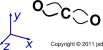
Similarly carbon dioxide is linear. It is conventional to diagram the molecule as O=C=O ... but that is somewhat misleading, because it suggests that all four bonds are straight and parallel to each other. A somewhat more informative diagram is shown in figure 25.
At this level of approximation, we can say that the four bonds depart the central carbon atom in the four tetrahedral directions, and then bend as necessary to terminate on the oxygen atoms. Two of the bonds lie are in the xy plane, while the other two lie in the xz plane.
Again it is easy to build a ball-and-spring model of this. The model depends on the fact that the bonds are bendable and springy. Pictures of such models can be found in reference 3.
Here’s why this is important: We expect a double bond to be stronger than a single bond, but nowhere near twice as strong (other things being equal). We can explain this by saying in a double bond, the bonds are bent and under stress, which costs energy. We can understand this energy as follows: The holes bear a positive charge, so there is some electrostatic energy involved in bending them closer together. There is also an increase in kinetic energy, since momentum depends directly on the curvature of the wavefunction, and kinetic energy depends on momentum squared. A tetrahedral arrangement of straight bonds has minimal potential energy (since the bonds are as far apart as possible) and minimal kinetic energy (since the bonds are straight).
The HCN molecule is linear, not bent, and it’s easy to see why. There is a triple bond to the nitrogen, specifically H−C≡N. Here (as always) we use a dash to represent two holes, i.e. the absence of antibonding electrons, not the presence of bonding electrons. We think about the shape as follows: start with the default tetrahedral configuration. The hydrogen is bonded to the A vertex. The nitrogen is bonded to the B, C, and D vertices. The nitrogen ion core sits at a location that is the average or the sum of the B, C, and D vectors. If you look at the geometry of the tetrahedron, you see that this puts the nitrogen directly opposite the hydrogen ... so we have an easily-visualized model of why HCN is linear.
Similarly, acetylene (H−C≡C−H) is linear.
A triple bond is even more highly stressed, more energetic, and more reactive than a double bond. Among other things, this explains why acetylene has remarkably high fuel value.
Consider the carbonate ion, CO3=. In the classical approximation, you can draw it with one double-bonded oxygen and two single-bonded oxygens. From this you can easily (and correctly) predict that it will be planar. At the next level of sophistication, moving beyond the classical approximation, there will be resonance, i.e. the three oxygens will “take turns” having the double bond, so the molecule is actually threefold symmetric. This configuration is called trigonal planar. In this case you can build three different not-quite-correct classical models; the correct symmetry is obtained by averaging these three.
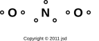
Let’s look at NO2. The constituent atoms are shown in figure 26.
There are seven holes, which is enough to make three and a half bonds. Note that any molecule where not all the electrons are paired is called a radical. There are many ways of drawing the bonds in such a molecule. At this level of detail, it is not at all obvious whether we should draw the molecule as linear or bent. Here are some facts that we might use as the basis for an analogy:
Hole-counting theory does not provide enough information to determine whether NO2 is linear or bent. The situation is somewhere between NOCl and CO2, so it could go either way. However, experiment tells us that it has a nonzero permanent dipole moment, so it must be bent. Therefore we choose to draw basis states as shown in figure 27.
The actual molecule is shown in figure 28. It is a resonant superposition of the two basis states shown in figure 27. Each oxygen is bonded to the nitrogen by one ordinary bond plus a partial bond with 3/4ths of a unit of bond strength.
We can contrast this with figure 29, which shows a hypothetical linear molecule. It has four “partial bonds”, each of which has 7/8ths of a unit of bond strength (for a total of 3.5 units). Hole-counting does not rule this out, but experiment tells us that this shape is disfavored relative to the bent shape.
The physics here can be partially rationalized as follows: There are many contributions to the overall energy. Resonance makes a contribution that tends to favor the linear structure. Meanwhile, bond-bending (as discussed in section 4.2.4) makes a contribution that tends to favor the bent structure. Hole-counting cannot tell you which of these contributions will win out.
Things get trickier if we consider bonding that involves elements in later rows of the periodic table, beyond N=3 ... but let’s not worry about that right now.
Some harder-to-explain examples (including SF6 and SF4) are discussed in section 5.
Here are some examples that don’t fit the simple pattern. It should be emphasized that there are millions of molecules for which you can draw a satisfactory bonding diagram without thinking very hard, but there are a few where you can’t.
One example that requires special handling is the nitro group, as found for instance in nitromethane (CH3)−NO2. Mindlessly playing the connect-the-dots game might produce the following diagram:
       O - O
        \ /
         N
         |
        HCH
         H
which is straightforward, elegant, symmetric, and wrong. The main problem is that it’s inconsistent with the IR spectroscopy data, which shows floppy, low-frequency bending of the O−N−O angle, inconsistent with closure of the three-member ring via an O−O bond. Instead it supports the following ringless structure:
            (-)        (-)
       O   O              O   O
       \\ /                \ //
         N(+)    <-->       N(+)
         |                  |
        HCH                HCH
         H                  H
I imagine there’s also NMR, NQR, and reactivity data confirming there’s a positive charge on the nitrogen.
To understand this result, you need to consider bond angles, as discussed in section 4. The natural angle for the O−N−O and O−O−N bonds should be close to the tetrahedral angle (109 degrees). Distorting these angles to form a 60−60−60 degree triangle is not energetically feasible.
To say the same thing more simply: In the real molecule, the oxygen atoms are significantly farther apart than the drawings above might suggest.
As a second peculiar example, consider SF6. Naive hole-counting tells us this molecule has 8 holes, which is enough for four ordinary bonds ... but there’s a problem, because there are six ligands. It is totally unacceptable to have 6 bonds with 2/3rds of a unit of bond-strength apiece, because QM tells us that using s and p orbitals gives us only four bonds, and only four places to put bonds. The only possible explanations for SF6 must involve contributions from some “supplementary” orbitals in addition to the conventional valence orbitals 3s and 3p. Hypotheses to be considered include 2p, 3d, 4p, and perhaps others. The energy levels of these supplementary orbitals is high, but not so wildly high as to make them completely inaccessible. This completely changes the hole-counting process, because there is a whole new set of bonding and antibonding molecular orbitals to be considered.
As a third peculiar example, consider SF4. Naive hole-counting tells us this molecule has six holes. That means it cannot have four ordinary chemical bonds; it can have at most three ... even though there are four ligands. That’s actually the right answer. Apparently the four fluorines take turns being bonded, with each one being bonded three quarters of the time. This is not different in principle from the nitro group discussed in section 2.4, or the carbonate ion discussed in section 4, except that in those cases the ligands take turns having a second bond, while in SF4 the ligands take turns having their first bond. You might imagine this makes SF4 somewhat unstable against disintegration, and you’d be right.
I don’t know of any useful convention for drawing a 3/4-strength bond.
We should also consider the hypothesis that SF4 has two ordinary bonds (each using a pair of holes) and two half-bonds (each using one unpaired hole). However, the lack of paramagnetism indicates this is not what happens. I don’t have any deep theoretical basis for predicting this, so for now let’s just consider it an observed fact.
Old-fashioned VSEPR predicts a remarkable “see-saw” shape for SF4. This would be considered a triumph for VSEPR, except that molecular dynamics studies indicate that that it’s not really a good description of what’s going on. I don’t know how to describe the shape of this molecule, and I certainly don’t have a simple way of predicting the shape.
We must also consider the hypothesis that d-orbitals are involved, which would throw off the hole count.
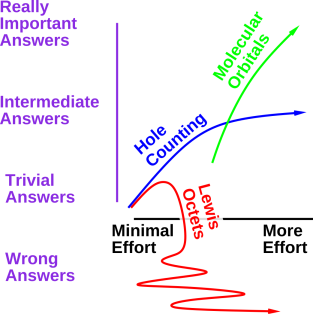
The relationship between the various available methods is shown in figure 30, which is a plot of “what you get out” (results) as a function of “what you put in” (effort).
The figure makes several important points, including:
Compared to Lewis dot structures, it appears that BABE and hole counting are better in every way, for the following reasons:
We shall see that the Lewis dot method is limited both as to domain and to range. By domain, we mean the class of molecules that it applies to. By range, we mean what it says about a given molecule. The tradeoff between domain and range is shown in table 1. In the table, domain runs horizontally, while range runs vertically.
| Molecule | CH4 | CO | O2 | C2 | B2 | |||||
| Number of Bonds | Yes | Yes | Yes | no | no | |||||
| All Electrons Paired | Yes | Yes | no | Yes | no | |||||
| Filled “Octet” | Yes | no | no | no | no |
Remember that this section is just an overview; supporting evidence will be presented in section 8 and later sections.
In table 1, you can that if we severely restrict the domain, keeping only the first column (namely simple hydrides such as CH4, NH3 etc.), then over this domain the Lewis method makes quite a range of successful predictions. If you want to sell the Lewis method as a theory of simple hydrides, that would be OK. Alas, people often try to sell it as something much more than that.
The second row of the table is important, because it represents not just the CO molecule but a wide class of electron-rich molecules, including most biomolecules. The Lewis method can predict the number of bonds for such molecules. However, the idea that atoms in such molecules have filled octets “just like neon” is hogwash, as we know from the spectroscopy data, from modern theory, and from many other lines of evidence.
Note that C2 is just barely outside the domain of electron-rich molecules. CO is sufficiently electron-rich, while C2 is not.
We now switch switch from a column-by-column discussion to a row-by-row discussion of the table.
As you can see from the top row of table 1, if we restrict the range to predictions as to number of bonds and nothing else, the domain gets bigger. If you want to sell the Lewis method as an unexplained, unprincipled mnemonic for predicting only bond order in electron-rich molecules made from certain elements in the upper-right corner of the periodic table, I might even buy it.
As a minor point of terminology, the term bond order is sometimes used to denote the distinction between single, double, and triple bonds. In this context the order is just a number, as in order-of-magnitude, or the order of a polynomial; it does not refer to the sequencing (or “ordering”) of the bonds left-to-right or anything like that.
The situation soon becomes ugly because most textbook authors cannot resist the temptation to “explain” the Lewis method in terms of atomic physics “principles”. They throw around physics ideas such as the energy of filled shells in neon, and then claim that “sharing” allows each atom in (say) the O2 molecule or the F2 molecule to have a filled shell “just like neon”. Scare quotes are necessary because usually nearly every word of such an “explanation” is false.4
There are of course other limitations. The basic Lewis method obviously has no hope of explaining a molecule such as SF6. Some authors try to patch this up in terms of an “expanded octet”.5 However, given that there aren’t really any octets in typical molecules, it seems pointless to talk about expanding something that doesn’t exist.
This section serves to put hole-bonding in context, relative to the widely-taught Lewis dot method.
Lewis dot diagrams have lots of problems, and it is possible to do much, much better, with zero additional work, using hole-counting and related methods as discussed in section 2.
Of course the Lewis dot method is not entirely without merit. Sometimes it makes correct predictions. For starters, as far as I can tell, it gives a satisfactory description of molecules in the sequence CH4, NH3, H2O, HF, Ne, which are all well-behaved molecules ... and conversely it correctly predicts that related entities such as CH3 are not well-behaved molecules under ordinary conditions. Another reasonably satisfactory example is NaCl, as discussed in section 10.2.
There are, alas, other cases where Lewis dot diagrams stubbornly and irreparably make wrong predictions.
Reference 4, from UC Berkeley, shows a conventional Lewis dot structure for the oxygen molecule, O2, which can also be called dioxygen. This is the way chemistry is taught in a lot of places, not just Berkeley. Figure 31 portrays the same idea, using a style I prefer because it is slightly more explicit. The black dots represent electrons. The reddish shaded areas represent orbitals. The proponents of such diagrams like to call attention to the following good points:
However, this diagram is nonsense. It cannot possibly be correct. The most obvious problem is that O2 is well known to be paramagnetic. If you pour liquid oxygen into the gap of a magnet, it will stick to the magnet. There is an animated GIF image of this in reference 6 and a nice still image in reference 7. Paramagnetism arises from unpaired electrons. Figure 31 categorically predicts that all electrons are paired. Therefore:
There have been various attempts to solve this problem. One attempt, from the University of Illinois, is shown in reference 8. Figure 32 portrays the same idea, using my preferred style.
This solves the paramagnetism problem, but creates several others.
So let’s try again. Hope springs eternal.
Reference 9 shows an oxygen molecule with one regular bond and two half-bonds. Figure 33 portrays the same idea, using my preferred style.
Alas this, too, has its problems.
We would prefer not to have a theory of chemistry based on rote dogma ("four legs good, two legs bad, eight dots good, ..."). Instead we would like to have a rule based on physics, mathematics, and logic.
For isolated atoms in the N=2 and N=3 rows, there is a valid octet rule, to wit: there are four orbitals near each atom, and each orbital can be occupied by at most two electrons (because of the exclusion principle). So far so good. The problem arises only when we try to extend this rule to the atoms in molecules. There arises a question of how to interpret the word “near” in this rule. The Lewis method chooses an interpretation that leads to DCBO (double counting of bonding orbitals) and this is irreparably wrong.
The five orbitals in figure 33 means either that the figure is wrong, or we need to entirely abandon DCBO in general and Lewis dot diagrams in particular.
Figure 34 shows the Lewis dot diagram for the sulfate ion. Remember, in this section, the dots in the diagrams represent electrons, not holes.
This isn’t particularly terrible. However, it is unnecessarily uglier and more complicated than the conventional diagram we saw in figure 15.
Within the Lewis formalism, just as in other formalisms, it is conventional to represent a bond by a dash, so when a pair of dots represents a bond we can replace it with a dash. In the case of the sulfate ion, the result is shown in figure 35.
This can be compared and contrasted with figure 15.
If you are interested in formal charge, figure 35 can be interpreted as assigning a +2 formal charge to the central sulfur atom, and −1 formal charge to each of the oxygen atoms. This is the same interpretation as we saw in section 2.1.7. It is consistent with the known electronegativity, and consistent with the known symmetry.
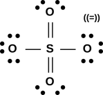
For some reason, figure 36 is commonly (albeit not universally) presented as “the” Lewis structure for the sulfate ion. It can be found in the Encyclopedia Britannica, on the wikipedia site, and in many textbooks.
This has the small advantage of having zero formal charge on the sulfur atom. In return it incurs the large disadvantage of violating the “Lewis octet” rule. There are six bonds to the central sulfur atom. Another disadvantage is that it violates the known symmetry; the molecule is observed to be tetrahedral, all four oxygen atoms are observed to be equivalent. It seems odd that even articles that say in the text that the oxygens are equivalent and tetrahedral persist in drawing a non-symmetric structure.
You could try to salvage the symmetry by saying the final structure is a quantum mechanical superposition of all the various ways of arranging the single and double bonds, leading to an average bond strength of 1.5 everywhere.
No matter what you do with the symmetry, we still have a violation of the “Lewis octet rule” since there are still six bonds to the central sulfur atom. Sometimes people try to wave away this violation by talking about an “expanded octet”, presumably involving the sulfur atom’s d orbitals. This is troublesome because it doesn’t explain why an octet might be “expanded” in some cases but not others.
In particular, the symmetry tells us there can’t be any d orbitals involved. The tetrahedral shape has the symmetry of an sp3 hybrid; any nontrivial admixture of d orbitals would change the symmetry.
Since there was never a rational physical basis for Lewis octets to begin with, don’t hold your breath waiting for a physical basis for the expanded octets.
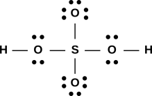
One possible Lewis structure for sulfuric acid follows the same pattern, as shown in figure 37.
Just as figure 36 is a modification of figure 35, there is a widely-seen alternative to figure 37, namely figure 38.
Again this violates the “Lewis octet” rule.
The “expanded octet” problem is not confined to sulfates; the various sulfonic acids are almost universally drawn with six bonds to the central sulfur atom. See section 7.4.
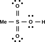
It is worth noting that the drawing of methanesulfonic acid in figure 18 (in section 2.1.8) shows single bonds everywhere, and only four bonds to the central sulfur atom.
That’s remarkable, because almost all references show this molecule with double bonds to two of the oxygen atoms, for a total of six bonds to the sulfur atom, as shown in figure 39.
Let’s consider the pros and cons of figure 39, according to the usual Lewis notions. We find (a) there is formal charge neutrality everywhere, which is good; (b) there are filled “Lewis octets” on the oxygen atoms on the outside of the molecule; although (c) the so-called octet rule has been seriously violated on the central sulfur atom.
Again as mentioned in section 7.3, sometimes people try to wave away the octet violation by talking about an “expanded octet”, presumably involving d orbitals.
In any case, in the BABE scheme, there is no problem, as discussed in section 2.1.8. Since we know that “filled Lewis octets” never existed to begin with, since we are not double-counting bonding orbitals, we have no fear of unfilled octets (on the oxygens or anywhere else).
Recall that one place where the BABE method diverges from Lewis octets is that the Lewis method stubbornly predicts that the O2 molecule has the O=O structure. It cannot accommodate the O÷O structure.
Here we have a second place where the methods diverge. The BABE method stubbornly predicts single bonds (and nothing but single bonds) in the sulfate ion, sulfuric acid, and methanesulfonic acid. In contrast, the Lewis method (as practiced by experienced professionals) usually makes a different prediction than the BABE method does concerning sulfate, and always (as far as I can tell) makes a different prediction regarding methanesulfonic acid.
This should have observable consequences in the electron density. The double bond has zero electron density along its midline. Is this observed in real life, or not? I don’t know for sure, but I predict not.
Here’s one reason why the BABE method cannot predict a double bond in these molecules. In going from figure 35 figure 36, we re-arranged some electrons. We took some electrons from a “lone pair” and used them to make another bond. This cannot happen in the BABE approach, because there are no lone pairs. The concept of lone pairs does not exist, so there’s nothing to re-arrange. You can’t just add another bond by pulling it out of the air, since that would change the overall electrical charge of the molecule.
In case you’re wondering whether there might be holes in a d orbital that could be used to form the additional bond, that’s a clever idea, but it won’t work. In these electron-rich molecules, bonds are holes in antibonding orbitals. All the low-lying d orbitals are bonding, and you can’t make bonds by putting holes in such orbitals. There are lots of games you can play with d orbitals, but none of them (so far as I can tell) increase the bond order in these molecules.
Note that the easy method of counting formal charge by counting bonds, as suggested in section 2.1.4, only works within the BABE formalism, i.e. when the bonds represent pairs of holes in antibonding orbitals in electron-rich molecules. In contrast, in the Lewis scheme, counting formal charge would be trickier, because we would need to account for lone pairs as well as bonds. This is another of the reasons why the BABE method is just plain easier.
If you are only interested in bond order, and you are sure you will never do any spectroscopy or any molecular structure calculations, you might conclude that Lewis dot diagrams are OK, for electron-rich compounds (with a few exceptions such as O2).
Please keep in mind that except for the hydrides mentioned in section 7.1, Lewis dot diagrams make false predictions about the spectroscopy and molecular orbitals of almost all molecules, not just oxygen. O2 is just the canary in the coal mine, in the sense that it is where we first noticed the problem. But it did not cause the problem, and ignoring the dead canary will not solve the problem.
As Kim Philby said: “To betray, you must first belong.” Applying this to the notion of filled Lewis octets, the fact that this fundamentally wrong notion makes some correct predictions about bond-order is a big part of what makes it so pernicious.
The bond-strength diagrams discussed in section 2 are firmly based on sound theory, as we now discuss.
This is called Molecular Orbital theory, or MO theory for short. Like most theories, it seems simple if you understand it, and formidably complicated if you don’t understand it. Like any good theory, watered-down, approximate, qualitative versions are available ... and that’s where we should start. Here then are some of the qualitative things we know about MO theory:
| The MO explanation is consistent with the paramagnetism data. | The Lewis dot diagram stubbornly predicts no paramagnetism, contrary to observations. |
| The MO explanation is consistent with the optical spectroscopy data. | The Lewis dot diagram has little to say about spectroscopy, and what it does say is categorically wrong. |
| The MO explanation is consistent with reactivity data, including things like B2 and Be2. | There are many cases – including B2 and Be2 – where Lewis dot diagrams make predictions that cannot be reconciled with observations. |
| The MO explanation is consistent with theory: atomic physics, quantum mechanics, and all that. | The Lewis dot approach was published about ninety years ago (reference 10), considerably before there was a comprehensive quantum-mechanical understanding of molecular bonding (reference 11). The Lewis approach cannot be reconciled with present-day theoretical understanding. |
A reasonably-accessible discussion of molecular orbitals, including a sketch of the energy-level diagram for O2, can be found in reference 2. Another useful source is reference 12, which contains energy-level diagrams for some interesting molecules (water, hydrogen fluoride, ammonia, methane, ethane, ethene, ethyne).
Among the things we learn is that the Lewis approach is a dead duck. We shouldn’t be surprised by this; it made the wrong predictions in figure 31, it was violated in figure 32, and it was toppled off its foundations in figure 9. The MO explanation tells us that these are not isolated or superficial mistakes, but instead result from a systematic and fundamental misconception. DCBO is just wrong.
| The MO explanation tells us that there should be eight molecular orbitals (not all of which will be filled). We know from classical physics and mathematics (Liouville’s theorem) that eight is the right answer. | In the Lewis dot approach, e.g. figure 31, we see six molecular orbitals, 2 unshared on the left, 2 shared in the middle, and 2 unshared on the right. We know (experimentally and theoretically) that this is the wrong number. |
Ironically enough, this means that while figure 9 has too many orbitals to be a valid Lewis structure (7 instead of 2+2+2), according to the molecular orbital explanation it doesn’t have too many – just the wrong kind.
This leads us to a key point: The data and the theory tell us that antibonding orbitals exist (as well as bonding orbitals of course). In particular, the two electrons that are responsible for the paramagnetism of O2 sit in antibonding orbitals, as shown in figure 21.
This in turn means that there is no hope of fixing the Lewis dot formalism, except by throwing it out and starting over, as was done in section 2. A proper theory cannot be based on DCBO. A proper theory must represent antibonding electrons (not just bonding and non-bonding electrons). A proper theory must have a way to take into account the energy levels of the molecular orbitals, to provide a foundation for applying Hund’s rules.
Consider the contrast:
| The old Lewis approach requires folks to believe in the unjustified – and unjustifiable – DCBO rule. It requires them to believe that O2 has six molecular orbitals (two on the left, two shared, and two on the right). | The new hole-bonding approach requires folks to believe in the well-founded notion of antibonding orbitals (as well as bonding orbitals) and degrees of occupation thereof. In fact O2 has eight molecular orbitals (four bonding and four antibonding). |
At this level of detail, the hole-bonding story is more truthful and less complicated than the Lewis story.
At this point,
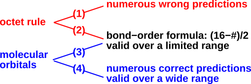
Let us examine what does – and what doesn’t – constitute evidence for the Lewis octet rule. This will help us understand its domain of validity. A high-level summary of the situation is shown in figure 40. The rest of this section is devoted to explaining the details.
When applied to a molecule like O2, the Lewis octet rule says that the number of actual valence electrons, plus the number of electrons involved in bonds, must add up to 16, i.e. one octet per atom. The point is that the electrons involved in bonds are intentionally double-counted. Since there are two electrons per bond, this leads to the bond-order formula:
| bond order = |
| (3) |
Now let us contrast this with a proper molecular-orbital explanation.
At the other end of the N=2 row, let us consider the would-be molecule Ne2. The MO diagram correctly predicts no Ne−Ne chemical bonding, because all eight molecular orbitals are filled. For every filled bonding orbital, there is a filled antibonding orbital, so there is zero net benefit in forming the molecule. This correctly contrasts with the F2 molecule, in which one of the antibonding orbitals is empty, leading to a net bond-strength of 1.
As we move another step to the left, we come to O2. Relative to F2, this has two fewer electrons, depopulating one more antibonding orbital. (Actually it half-depopulates two such orbitals.) In any case the result is a net bond-strength of 2.
Moving again to the left, in N2 we have three fully-depopulated antibonding orbitals, for a bond-strength of 3.
For the four cases Ne2, F2, O2, and N2, we find that equation 3 summarizes the facts. Note the word “summarizes”.
The point is that equation 3 only summarizes the four facts, without explaining any facts whatsoever. It’s at best a mnemonic. It’s little more than numerology. To see the distinction between summarizing and explaining, just extend the sequence one more step to the left: When we get to C2, we depopulate another orbital ... but this time we depopulate a bonding orbital, reducing the bond-strength to 2.
The bond-strength peaks at 3 at N2. From there, moving either to the left or to the right causes bond-strength to decrease.
Equation 3 gets worse and worse as we continue moving to the left across the N=2 row.
So let’s see how the contestants have scored:
To repeat: equation 3 summarizes the data over a narrow range, but is not (by itself) an explanation. Explaining the formula in terms of octets only makes things worse. MO theory explains equation 3, explains its limitations, and explains lots more besides.
This continues the discussion that began in section 3.1.
It is worth noting that the Aufbau principle is utterly incompatible with the Lewis octet idea. Let’s do an example, starting with O2. The Lewis “theory” tells us that each atom in the molecule will have an octet of electrons “around” it. If we now construct F2 in accordance with the Aufbau principle, we leave the oxygenic electrons alone, and add two more electrons. There are now more than eight electrons “around” each atom.
For most molecules, this is an inescapable conflict. Either the Aufbau principle is wrong, or the Lewis octet idea is wrong. (The wrongness of the Lewis octet idea is discussed in section 7.)
| The Lewis model explains bond order in terms of bonding pairs and non-bonding pairs. | MO theory explains bond order in terms of bonding and antibonding. |
| If you think in terms of bonding and non-bonding, there is no Aufbau-compatible way to explain how F2 can have more electrons but less bond strength. | It is perfectly compatible with the Aufbau principle to say that when we go from O÷O to F-F, we leave the bonding levels alone but add electrons to an antibonding level. |
There is a big difference between antibonding and non-bonding. There is a big difference between BABE and BNBE (i.e. Lewis dot structures).
Almost all scientific results, experimental and theoretical, are approximate and imperfect.
One criterion for judging scientific approximations is that they ought to be controlled approximations. That is, the error ought to be small, we ought to have an upper bound on how big the error is, and we would like to have a way of making the error smaller if and when we need to.
Lewis dot diagrams do not do well under this criterion. The Lewis octet rule seems to be an all-or-nothing proposition. Either the O2 molecule has just six molecular orbitals, or it does not. In fact it does not, as we know from the paramagnetism data, the spectroscopy data, et cetera. So Lewis dot diagrams must be put into the same category as the oyster/R mnemonic.
Another rule of good scientific practice is to be up-front about whatever approximations are being made. This is where the most immediate improvements can be made. If you feel you must draw Lewis dot diagrams, go ahead, but make sure the audience understands that:
Another rule of good scientific practice asserts that it is bad manners to criticize a result for being imperfect unless you’ve got something better to suggest. In this case the suggestion is to use the bond-strength diagrams described in section 2, which are preferable to Lewis dot diagrams in every way.
Similarly, the bond-order formula equation 3 is valid over a limited range, but still has more validity than the Lewis octet picture. It can be seen either as a narrow corollary of the molecular orbital explanation, or it can be used on its own merits as an empirical / phenomenological / mnemonic / numerological rule.
It is perfectly possible to visualize the results of the bond-order formula. You can draw pictures of molecules including F−F, O÷O, N≡N, C/=\C, B\;/B, and Li∼Li ... without connecting any of this to “molecular octets”. We connect this to correct theory by saying that each − or ∼ represents one unit of bond strength. A ∼ represents a filled bonding orbital, while a − represents an unfilled antibonding orbital.
Things go awry when people try to use the successes of the bond-order formula as evidence for the Lewis octet rule, by back-tracking along arrow (2) in figure 40. It is not logical to follow arrow (2) while ignoring arrows (1), (3), and (4). It is not fair to pay attention to the occasional fortuitous successes of the DCBO rule, while ignoring its failures and ignoring the many successes of competing hypotheses.
To say the same thing in other words: What many people claim as successes for the molecular octet rule are nothing of the sort; they are really just successes of the bond-order formula for electron-rich molecules – equation 3 – with no necessary connection to the molecular octet rule.
The Hall effect (reference 13) was discovered in 1879. It was found that some metals (e.g. aluminum and magnesium) have positive Hall coefficients, indicating positively-charged majority carriers – what we would nowadays call holes. Note that this was many years before the date conventionally assigned to the “discovery” of the electron (reference 14).
The notion of holes is central to any discussion of solid-state electronics. This goes back to Peierls’s 1929 explanation of the Hall effect (reference 15).
Holes have been part of quantum field theory since Dirac’s epochal work in 1930 (reference 16, page 293):
The annihilation of a negative-energy electron is to be understood as the creation of a hole in the sea of negative-energy electrons, or the creation of a positron.
The idea of holes in the context of bonds between atoms is not new, either. In 1969, Baym (reference 17, page 454) remarked that a halogen could be regarded
... as having a weakly bound “hole” which also easily forms chemical bonds.
I’m not quite sure why he put the word hole in scare quotes.
Let’s consider a crystal of NaCl. It exhibits ionic bonding, in contrast to the covalent bonding in (say) a silicon crystal. It can be described reasonably well in classical terms: the Na+ ion and the Cl− ion are modeled as classical hard spheres (of appropriate sizes), and they are held together by Coulomb interactions.
This is consistent with the idea of Lewis octets, in the sense that the Na+ ion and the Cl− ion can be explained in terms of filled atomic octets. (Remember, atomic octets actually have some basis in fact, whereas molecular octets almost never do.)
It must be emphasized that the Coulomb interaction between ions is quite different from the covalent bond. In the real world, some bonds exhibit a mixture of ionic and covalent character. NaCl crystals are near the ionic extreme, while silicon crystals are at the covalent extreme.
Coulomb’s law can be expressed in a variety of equivalent forms. These include:
| V(r) = [ |
| ] |
| (4) |
where V(r) is the voltage (i.e. electrical potential) at location r due to a charge Q at the origin. The quantity in square brackets is a universal constant, called Coulomb’s constant. It is occasionally written kC but more commonly as 1/(4 π є0).
An equivalent expression is:
| F(r) = [ |
| ] |
|
| (5) |
where F(r) is the force on a charge q at location r due to a charge Q at the origin. The r/|r| factor is a unit vector in the r direction. The force is directed radially outward if Q and q have the same sign.
The Coulomb interaction depends on the charge (but not the mass) of the particles. It is a long-range force, in the sense that the interaction energy falls off like 1/r. In contrast, the size and strength of the covalent bond depend on the mass (as well as charge) of the electron. The covalent bond is necessarily a short-range interaction: at large distances the wavefunction falls off exponentially, at a rate determined by the mass of the electron.
Coulomb’s equation tells us the electrostatic potential energy, but we must also include the kinetic energy. We must include the kinetic energy if we are to have any hope of explaining many of the most well-known and important chemical facts, including:
Charles-Augustin de Coulomb died in 1806, more than 100 years before the advent of quantum mechanics. Therefore speaking of a “Coulombic” model rather strongly implies a classical model. We know that any correct description of covalent bonding requires non-classical ideas – far, far beyond what you can get from equation 4.
Some people who are fed up with Lewis dot diagrams try to solve their problems by suggesting we can describe everything (or almost everything) in terms of “Coulombic” models. This is not a good idea. Let’s be clear: Talking about a “Coulombic” model of the water molecule or the ethylene molecule is at best misleading. It is at best an abuse of the terminology.
Coulomb’s law is part of the description of any chemical bond (including covalent as well as ionic), but is equally true that bolts are part of a car. We don’t talk about the “bolt” model of how cars work, and we shouldn’t talk about the “Coulombic” model of bonding, except perhaps for ionic compounds such as NaCl. Coulomb’s law is a law of physics, but it is only one law among many; it is not a complete description.
(In contrast, it is OK to talk about a “quantum mechanical” model. That’s because QM explicitly incorporates all the other laws of physics. On the RHS of the Schrödinger equation we find the Hamiltonian, which includes all the contributions to the energy. In contrast, the Coulomb energy calculated using equation 4 is just one contribution to the energy, one contribution among many.)
There is nothing you can do via Lewis dot structures that you can’t do at least as easily and at least as accurately via hole-counting. Hole counting, within its domain of applicability, is based on sound theory, whereas Lewis dot diagrams are based on a fairy tale.
There are many cases where Lewis dot diagrams predict bond-order in agreement with the facts. However, this agreement must be considered fortuitous, because there are also many disagreements that ought not be overlooked. The method recommended here – accounting for antibonding orbitals as well as bonding orbitals – retains all the good features of Lewis dot diagrams while getting rid of the disagreements.
| There is an octet rule for atoms that is reasonably well founded in atomic physics for a single row-2 atom. Truly there is something special about the complete octet (i.e. closed shell) in neon. | Chemistry is primarily about molecules, not isolated atoms, especially not noble-gas atoms. For molecules, the Lewis approach couples the octet idea to DCBO (double counting of bonding orbitals), which is a disaster. |
| In reality, there are eight valence-shell molecular orbitals in molecules such as O2. This is the starting point for the theory of chemistry described here. This is the right answer. | The Lewis approach says O2 has only six molecular orbitals: two on the left, two shared, and two on the right. This is the wrong answer. |
| Naive hole-counting won’t tell you whether O÷O or O=O is preferable. Making no prediction about this question is better than making a wrong prediction. We leave the door open for other theoretical and/or experimental information to decide the question. | Lewis octets stubbornly predict O=O, in defiance of the well-known facts. There is no way to draw a Lewis octet that fits the facts. |
| Hole-counting gives a good accounting of its own limitations. It is easy to understand that naïve hole-counting works in electron-rich molecules, including a very wide range of important biomolecules. Meanwhile, it is easy to see that slightly less-naïve accounting is needed to explain C=C and other systems that are not electron-rich ... without in any way contradicting what was said about electron-rich systems. | Lewis “theory” does not explain its own limitations. There is no way to explain C=C in terms of Lewis octets, nor any good way to explain why not. Octets are either a fundamental principle, or they’re not. If the octet “principle” explains N2, why doesn’t it explain O2 or C2? |
| In every case where Lewis dot diagrams make correct predictions, hole-counting makes the same predictions (i.e. the correct predictions) with the same amount of effort, or less. | Lewis dot diagrams are, of course, better than nothing. The successes of Lewis dot diagrams area a subset of the successes of hole-counting. |
| Hole-counting is based on molecular orbital theory. It is a shorthand, summarizing (not supplanting) some well-established facts. | The Lewis dot diagram scheme is based on DCBO, and on the neglect of antibonding, and on other assumptions that are inconsistent with what’s really going on in the molecule. It is a miracle that Lewis dot diagrams make as few wrong predictions as they do. |
| Within MO theory we can visualize bond order just as easily as we could using Lewis dot diagrams. For instance we can draw N≡N, where each dash represents an unfilled antibonding orbital. In any case where you could have drawn a Lewis dot diagram, you can draw a bonding diagram consistent with MO theory – and consistent with the facts – with the same amount of effort. In other cases, the correct diagram is slightly more work, but it’s a small price to pay for correctness. | Lewis dot diagrams are easy to draw, easy to visualize, compact, and elegant ... but rife with error. |