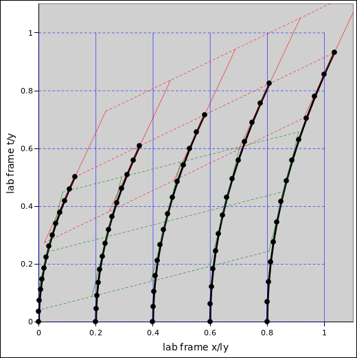
Figure 1: Independent Hyperbolic Rocket Trajectories
Suppose we have an object with some large length (L) undergoing a large constant acceleration (a). We consider the relativistic case, where La/c2 is not small compared to unity. As always, length means proper length, and acceleration means proper acceleration.
It is well known that the world-line of pointlike object undergoing constant acceleration is a hyperbola. When we generalize to a larger object, we find a few features that may seem non-obvious at first, but can be given a simple interpretation in terms of the geometry of spacetime. We call particular attention to the geometrical center of the hyperbolas.
We shall see that in order for the object to maintain its shape, different parts will need to accelerate at different rates. This can be considered a generalization of the notion of centrifugal force, as applied to the case of a rotation in the xt plane.
The discussion here assumes you already know the basic principles of special relativity from the modern point of view. If in doubt, please review reference 1 and reference 2 before proceeding.
By way of example, let’s consider a rocket with proper length L = 0.8 light-years, undergoing a proper acceleration |a| = 1gn (i.e. one Earth gravity).
As a warm-up exercise, we consider the following simplified situation. We replace the original rocket with a cluster of five separate, independent sub-rockets, equally spaced. The overall length of the cluster matches the length of the original rocket. We ignore any mechanical connection between the sub-rockets. Each sub-rocket is considered to be pointlike, i.e. not an extended object, very unlike the original rocket. The initial location of the sub-rockets is shown along the bottom of figure 1. These are the starting points of the five trajectories. The back of the cluster starts at x=0 and the front of the cluster starts at x=0.8 light-years.
The cluster is initially at rest. Thereafter, the acceleration is |a| = 1gn i.e. 9.8 m/s/s. That’s the proper acceleration, measured at each instant in an inertial frame that happens to be instantaneously comoving with the sub-rocket. We take a snapshot every two weeks for 26 weeks, i.e. about half a year. The snapshots are shown by the black dots in figure 1.
The spreadsheet used to create this figure is cited in reference 3.
Each sub-rocket shuts down at the end of 26 weeks. Each sub-rocket does this independently, according to its own measure of proper time.
Each trajectory is the world-line of one of the sub-rockets. Each trajectory, when plotted in the terrestrial lab frame (or any other inertial frame) is a hyperbola. Hyperbolic motion is characteristic of constant proper acceleration. See reference 4 and reference 2 the next level of detail on this.
In the figure, dashed blue lines are lines of constant t@L, i.e. constant time in the terrestrial lab frame, labeled in units of years. Solid blue lines are lines of constant x@L, i.e. constant position in the terrestrial lab frame, labeled in units of light-years. (The speed of light would be a 45∘ straight line in this diagram, but this is not explicitly shown.)
Meanwhile, dashed red lines are lines of constant t@R, i.e. constant time in the inertial frame comoving with the cluster, specifically the midpoint of the cluster at the 26-week mark. Solid red lines are lines of constant x@R, i.e. lines of constant position in the inertial frame comoving with the midpoint of the cluster at the 26-week mark.
After the experiment is over, we collect all the data and analyze it from the point of view of the middle sub-rocket. Everything was fine at the time when the rockets started firing. Everybody started firing at the same time. However, things went haywire at shutdown time. According to the guy in the middle, the guy at the back of the cluster shut down late. This can be explained in terms of gravitational redshift.
This monkey-business with the time is not really a problem. All observers can correct for the gravitational redshift and proceed accordingly. Note that it would be inelegant and possibly very misleading to say that one of the clocks “ran slow” while another “ran fast”. There is nothing wrong with any of the clocks. Each one keeps the correct time as it moves along its own world-line. Keep in mind that a clock is more like an odometer than a ruler. There is no more reason for different clocks to agree than for different odometers to agree, when they have followed different paths. See reference 1 and especially reference 5.
What’s far more serious is that at the end of the maneuver, the cluster is not the same shape as when it started out! The length between sub-rockets has increased. You can see this by comparing the trajectories to the contours of constant x@R. As always, shape is defined in terms of proper length, as measured along a contour of constant time in a frame comoving with the cluster. (Every sub-rocket has the same acceleration and the same notion of proper time. To compare apples to apples, we should compare things at a particular phase of the maneuver, e.g. the halfway point, or the end of the maneuver. At any given phase of the maneuver, every sub-rocket is moving at the same speed, so there is no trouble finding a suitable comoving frame. For more about how to keep time in an extented object, see section 3.5.)
This was pointed out by Dewan and Beran (reference 6) and eventually became known as Bell’s Spaceship Paradox (reference 7 and reference 8).
Different sub-rockets may disagree about “whose fault” it is that the shape is broken, but they will all agree that it is broken. During the manuever they may disagree about how badly it is broken, due to the breakdown of simultaneity at a distance. However, if we wait until the maneuver is long over, after all sub-rockets have been freely coasting for a time long compared to L/c, they will agree as to the details of how badly the shape is broken.
Therefore the cluster is not a very good model of a rigid extended object. We remedy this problem in section 2.2.
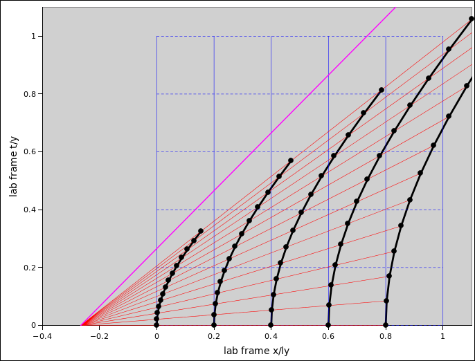
One way to keep the cluster from getting longer would be to make the sub-rockets no longer independent. Connect them with mechanical struts. All during the maneuver, there would be stress in the struts, as they provide the force to keep the spacing between sub-rockets equal to the desired amount of proper length. The result is shown in figure 2. Compared to the case of independent sub-rockets, the tail of the rigid rocket needs a greater acceleration for a lesser time. The nose needs a lesser acceleration for a greater time.
If you want to minimize the amount of stress in the struts, you can make the sub-rockets non-identical. The sub-rockets to the rear are commanded to put out more thrust for a shorter time, while sub-rockets near the nose are commanded to put out less thrust for a longer time.
In this figure, the spacing between dots represents an equal fraction of the trip, not an equal amount of elapsed time. The dot-to-dot spacing is 1/13th of the total trip. At the middle of the rocket, this corresponds to two weeks of proper time; elsewhere it is some other amount of proper time.
The green grid corresponds to an inertial frame comoving with the rocket at the mid-time of the maneuver. For the sub-rocket in the middle of the cluster, this corresponds to 13 weeks.
Note the following contrast:
| In figure 1 we have five hyperbolas, all with the same shape, including the same curvature, just shifted in position relative to each other. | In figure 2, we have five hyperbolas shifted and scaled so that they all have the same asymptote, and the same center. |
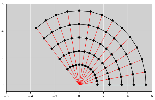
The center of the hyperbolas is shown explicitly in figure 3. The center sits at a point c2/a aft of the midpoint of the rocket. The hyperbolas share a common asymptote, namely the 45∘ magenta line shown in the figure.
In this figure, the acceleration at the middle of the rocket is |a| = 2gn (in contrast to previous figures, where it was |a| = 1gn).
We see that in spacetime, there is a fairly simple geometric structure to the accelerated motion of a rigid object.
As mentioned in section 2.2, maintaining the shape of the extended object requires some stress or some other way of providing unequal accelerations.
This is roughly equivalent to centrifugal force. If you rotate a solid object in the xy plane, there are mechanical stresses. It shouldn’t be too surprising to discover that rotating something in the xt plane also produces mechanical stresses. A boost, after all, is nothing more than a rotation in the xt plane. See reference 1 and references therein for details on this.
The relativistic stress is oriented along the direction of acceleration, which is also the direction of motion. (This stands in contrast to a steady centrifugal situation, where the acceleration and the stress are perpendicular to the motion.)
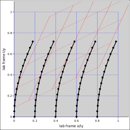
This motion in spacetime (in the xt plane) has an analogy in ordinary Euclidean space (in the xy plane). Consider five members of a marching band, marching line abreast, pivoting around a point. This is shown in figure 4.
The marchers form a rigid “extended object”, namely a line with constant spacing between marchers.
First criterion: The situation is relativistic whenever La/c2 is not small compared to unity. That is to say, the situation is relativistic whenever the length is not small compared to c2/a, or (equivalently) the acceleration is not small compared to c2/L.
This criterion is frame-independent and not sensitive to velocity. It does not care whether or not the velocity is comparable to c in this-or-that frame. Therefore it might be argued that this is really a general-relativity problem, even though it can be solved using the methods of special relativity.
In the non-relativistic limit, where La/c2 is small, your intuition that all parts of the object should accelerate at the same rate is correct. This corresponds to a situation where the shared center of the hyperbolas is a very long ways aft of the rocket. This situation could be handled by the simplified methods of section 2.1.
Note: For one earth gravity, the characteristic length-scale (c2/g) is 1.33 light-years. The characteristic time-scale (c/g) is 1.33 years. This is an amusing numerological coincidence; there is no reason why the earth’s gravity and the earth’s year should have anything to do with each other, but they wind up being comparable.
Second criterion: If the acceleration continues for long enough that the velocities become comparable to c in whatever frame you are using, that raises special-relativity issues that must be handled in the usual way.
A correct description of relativistic acceleration should guarantee that at the end of the maneuver, the rocket is the same size and shape as when it started, and all parts of the rocket should be moving at the same velocity. We should check that our solution meets these requirements.
As preparation for checking, let’s quickly review some fundamental ideas of special relativity. See reference 1 for details on these ideas.
| (1) |
This is analogous to a rotation in Euclidean space, where
| (2) |
| In a spacetime diagram, some things are easily and naturally represented with very high fidelity. One such thing is the correspondence between slope and reduced velocity. A slope of 1 on the diagram corresponds to a reduced velocity of 1 (in spacetime units), by which we mean v=c (in conventional units). |
Because the spacetime diagram is drawn on paper in a spacelike
plane, the geometry of the diagram will never exactly match the
geometry of spacetime. However, we can interpret
things correclty with the help of some simple
translations. One thing that needs translating
is angles:
where this θ is the apparent angle, the representational angle, as seen on the spacetime diagram. |
These ideas, plus the geometry of figure 3, should suffice to convince you that our description of relativistic acceleration is correct and complete.
If for some reason you prefer algebra to geometry, we can do that also. Let’s do that now:
Along any one of the red lines in figure 3, we have 6 colinear points, including the center (O) and the five sub-rockets ({R1, R2, R3, R4, R5}). The separation vector between any sub-rocket and the origin can be expressed in terms of its components in the lab frame:
| (4) |
where k1 and k2 are constant throughout the maneuver, independent of ρ. This is true by construction; we require each sub-rocket to follow a trajectory of this form. We also require that the rapidity grow linearly with time:
| (5) |
where ai is the proper acceleration of the ith sub-rocket, and τ is the proper time. The acceleration is inversely proportional to the distance (Di) from the center. In fact, in all cases,
| (6) |
Last but not least, we require each sub-rocket to end the maneuver at a time that is directly proportional to the distance from the center.
| (7) |
As a consequence, the final rapidity is the same for all sub-rockets. The ones near the tail undergo a greater acceleration for a lesser amount of time.
Hence the vector separation at the end of the maneuver is:
| (8) |
and the gorm is:
| (9) |
So we have proved one of the key requirements: The rocket keeps its shape.
Meanwhile the reduced velocity of sub-rocket A is
| (10) |
where the bottom line is independent of i ... which means that all sub-rockets have the same velocity at the end of the maneuver. This completes the proof.
As a further check, consider the non-relativistic limit. When ρ is small compared to unity, equation 10 reduces to v = a τ, which is the expected classical non-relativistic result.
Seriously, you should be able to obtain these results mathematically ... and you should also be able to see the results geometrically, without doing the math. Each of the five trajectories is a scaled version of the others. A scaled hypberbola is still a hyperbola. And since we are scaling the t-direction and the x-direction by the same factor, the velocity is unaffected.
Operationally, a good way to configure things is as follows: Start by choosing a “control point” somewhere along the rocket. (In the previous examples I used the middle of the rocket as the control point, although using the tail might be slightly safer.) Then choose the acceleration you want for this point, and the total duration of the maneuver as seen at this point. From that you can determine the center of they hyperbola. From that you can construct everything else, including the acceleration and the timing for every other point.
In figure 3, each of the red lines is a contour of constant time. For simplicity, let’s focus attention on the last red line, even though similar words would apply to any of the others.
At the end of the maneuver, the various sub-rockets agree that the red line connecting them is a contour of constant time. This makes sense, since they all have the same velocity. They do not, however, agree as to what time it represents. That is not as crazy as it sounds. It corresponds to the familiar idea of time zones. When somebody says that the championship game will be broadcast starting at 7:00 Eastern time, 4:00 Pacific, we understand that the time of the event is fundamentally the same – even though the clock-readings differ from place to place.
As a general rule, a constant offset between clocks has no effect on the physics. This is an example of gauge invariance. The laws of physics depend only on derivatives of the time, not the absolute time itself.
It is possible for the various sub-rockets to figure out what time-zone they are in, and to correct for this. It is therefore possible for them to agree that the final red line – the shutdown – occurs at the same time everywhere, in terms of the corrected time.
Alas, the time-zone analogy is imperfect. Consider the contrast:
| Suppose there are two twins. They both start out in the Eastern time zone. They synchronize their clocks. One twin travels to the Pacific time-zone. We neglect some exceedingly small relativistic effects associated with the travel. To use the Pacific time-zone, the traveling twin has to reset his clock. This makes his clock-readings inconsistent with the laws of physics. That is to say, there will be glitches in the clock-reading that are incompatible with the time derivatives that we see in the basic laws of motion, laws of electrodynamics, et cetera. | In figure 3, at the beginning of the maneuver (the bottom red line), everybody is in the same time zone. At the end of the maneuver (the top red line), different sub-rockets are in different time-zones. Remarkably, none of the clocks were reset. Each of the clocks carried out its duties according to the laws of physics. |
| Resetting a clock is in some sense arbitrary and artificial. Whenever it happens, there is a clear, classical explanation for what happened: Somebody reset the clock. | The offset between the clock-readings in the various sub-rockets must be explained in terms of relativity. There is no classical explanation. |
The offset between clocks depends on the magnitude on the acceleration, the duration of the acceleration, and the distance between clocks. The same phenomenon shows up in the case of the traveling twins, if one of them travels out and back at relativistic speeds (for a long-enough distance), as discussed in reference 5. This is fundamentally a general-relativity problem, although in simple cases it can be handled using the methods of special relativity.
If this offset seems counterintuitive, it is probably because you are assuming that two clocks that start out in agreement should remain in agreement. This assumption is correct in the non-relativistic limit but not otherwise. There is not the slightest reason why it should be true in general. A clock is analogous to an odometer, and odometers that start out in agreement do not generally stay in agreement. For details on this, see reference 5.
In another context, the same physics produces the phenomenon we call the gravitational redshift. When the rocket is accelerating, a reference frame attached to any of the sub-rockets is an accelerated frame. In accordance with Einstein’s equivalence principle, there will be a gravitational field in this frame.
Reprinted in: J.S. Bell,
Speakable and unspeakable in quantum mechanics
pp. 67–80
Cambridge University Press (1987)