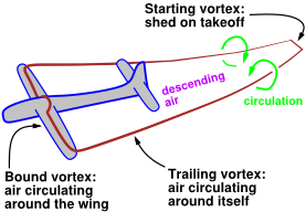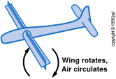
Figure 1: Paddle-Wing Airplane
Copyright © 2007 jsd
Several people have been asking questions about the the airflow near a wing. Where does the momentum come from? Where does the energy come from? What is a vortex and why should I care? Why does one dimensional-analysis argument give the wrong answer, while another dimensional-analysis argument gives the right answer?
This discussion is the intermediate step in the following sequence:
Probably the best place to start is with the paddle-wing airplane as shown in figure 1.
See reference 1 for more on this.
Suppose it has no airspeed; it is just hanging there, supported by a string. Obviously (by symmetry and ten other reasons) with no airspeed, it produces no lift. It just circulates the air around and around. The velocity field falls off like 1/r.
Now give the thing some forward airspeed. Thereupon it will produce lift. The magnitude of the lift is given by the Kutta-Zhukovsky theorem,
Lift = airspeed * circulation * density * span
as discussed in reference 1, subject to some mild simplifying assumptions as detailed below. It’s an easy exercise to prove this; see e.g. reference 4 page 176.
So here we have a model of lift production which obviously works just fine in a fluid where compressibility effects are negligible, such as water. It turns out that air works the same way: at speeds not near or above the speed of sound, any changes in density are unimportant. For a discussion of why this is, refer to reference 1 .
Returning to the main idea: a vortex produces no lift when it is stationary, but positive lift when it moves. This is probably not what most people would have guessed. But it’s true.
As the saying goes, "Learning proceeds from the known to the unknown." I realize that most people have rather little familiarity with vortices. Therefore I implore you: before reading the rest of this note, grab your egg-beater or your electric drill, make a paddle for it, and stir up some vortices in a big tub of water (the bigger the better). Convince yourself that a vortex is a natural, well-behaved, long-lived flow pattern. Convince yourself that the velocity in the vortex is tangential and proportional to 1/r. (This is very unlike a disk, where the velocity is proportional to r.) (This is also a remarkably slow fall-off; the velocity is significant surprisingly far away.)
It turns out that almost any flow pattern worth discussing can be considered a superposition of vortices plus some overall uniform flow. On the opposite side of the same coin, if you dream up some arbitrary non-vortex pattern, it will almost certainly not satisfy the equations of motion. If you guess that the fluid at point X has velocity V, then you have to say what happens to the fluid at point X + V dt .... How does the fluid there get out of the way of the fluid you are sending in? And then you have to balance the equations for pressure and momentum.
In any case, you can take it as an experimental fact that wings are really, really good at stirring up circulation.
Figure 2 represents a cross section (taken perpendicular to the wingspan) of the flow pattern near the wing.
         X    Y    Z     A    B    C

                _  _  >  _  _
             /                 \
                  _ _ > _ _
                /           \
          /         __>__          \             | up
              /    /     \    \                  |
                  /       \                      |____right
       |    |    |    O    |   |    |
                  \       /
              \    \__<__/    /
         \                         /
                \ _ _ < _ _ /

             \  _  _  <  _  _  /


         X    Y    Z     A    B    C
We are making the usual assumptions, including
Now let’s mark off some columns in space, centered on the letters XYZABC in figure 2, and calculate the upward momentum in each column.
As we move farther from the center of the vortex, the velocity goes down, but a bigger piece of the circular flow pattern "aligns with" the column. The result is that the upward momentum in each column is the same for all columns, except for a possible minus sign. (For homework: check this assertion. It’s easy. Hint: Separation of variables.) Specifically:
   upward momentum:  ....  1,  1,  1, -1, -1, -1 ....
   in column:        ....  X   Y   Z   A   B   C ....
To get the total momentum, we can try to add up those numbers, summing over all columns. You might guess that if everything is nice and symmetric, the sum of all those +1 and -1 terms adds up to zero. But don’t be too sure of that.
Now suppose we move the vortex a little to the left. We do not move the column-markers, so now the flow-pattern that used to be in column Z has moved to column Y. The momentum is now given by:
   upward momentum:  ....  1,  1, -1, -1, -1, -1 ....
   in column:        ....  X   Y   Z   A   B   C ....
This ought to make you very suspicious. There are two ways to look at this:
It turns out that both of these are viewpoints are defective. We know that it is mathematically improper to sum a non-convergent series. By re-arranging the terms you can get any answer you want. The problem is that the question, as formulated above, is unphysical. We need to go back and reformulate things so that this unphysical non-convergent series does not arise.
It turns out that it would be mathematically (not just physically) impossible for a vortex to have loose ends. Vortex lines always form closed loops, like magnetic field lines. The way it works in an airplane is shown (to a reasonable approximation) in figure 3. a
To a further reasonable approximation, we can divide this vortex loop into four segments:
So let’s bring the starting vortex into the picture; we continue to ignore the trailing vortices for a moment. The whole loop spins in unison, but the starting vortex segment is on the opposite side of the loop from the bound vortex segment, so if you take a cross section, they appear to spin in opposite directions, as shown in figure 4.
   W    X    Y    Z     A    B    C    D    E    F    G    H    I

         _ _ > _ _                                _ _ < _ _
       /           \                            /           \
           __>__                                    __<__
     /    /     \    \                        /    /     \    \
         /       \                                /       \
    |   |    O    |   |                      |   |    O    |   |
         \       /                                \       /
     \    \__<__/    /                        \    \__>__/    /

       \ _ _ < _ _ /                            \ _ _ > _ _ /

           bound                                   starting
           vortex                                   vortex


   W    X    Y    Z     A    B    C    D    E    F    G    H    I
The air in the region between the two vortices is descending; both vortices contribute to inducing this downward flow.
In contrast, outside this region, there will be opposite contributions from the two vortices. In (say) column X in figure 4, the bound vortex will contribute one unit of upward momentum, while the starting vortex will contribute one unit of downward momentum.
All in all, the upward momentum in each column is:
             bound
             vortex (before it moved)
               |
  .... +1 +1 +1 -1 -1 -1 -1 -1 -1 -1 -1 -1 -1 -1 ....
  .... -1 -1 -1 -1 -1 -1 -1 -1 -1 -1 -1 +1 +1 +1 ....
                                       |
                                     starting
                                     vortex

          bound
          vortex (after it moved)
            |
  .... +1 +1 -1 -1 -1 -1 -1 -1 -1 -1 -1 -1 -1 -1 ....
  .... -1 -1 -1 -1 -1 -1 -1 -1 -1 -1 -1 +1 +1 +1 ....
                                       |
                                     starting
                                     vortex
We see that the symmetry argument in viewpoint (b) above was completely wrong. The situation is not symmetric with respect to the center of the bound vortex. The symmetry is broken by the presence of the starting vortex, which does not move when the bound vortex moves.
It’s true: by stretching the distance between the two vortices, we really can create new downward momentum.
You can double-check the mathematics to show that the integrals converge. Fortunately, the physically-correct integrand goes to zero fast enough. No re-arrangement of terms in any non-convergent series is required, when the two vortex segments are considered.
If you bring the trailing vortex segments into the picture, they tell the same story. They reinforce each other to induce downward velocity in the region between them, and they cancel each other to produce zero total downward momentum in any column outside that region.
If we take all four vortex segments together, the picture makes a lot of sense. The roughly rectangular area bounded by the four segments is pierced by columns of descending air. Outside that area, the total momentum of each column is zero (although there is all sorts of commotion if you look closely within a column).
Note: Everything we just said was true, but actually proving it is true involves some tricky mathematics. One source of trouble is the fact that the velocity field of a long vortex line falls off like 1/r, which is a very slow fall-off, so even far-away bits of vortex can make surprisingly large contributions to the column momentum.
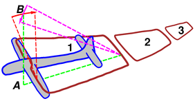
One technique that you may find helpful is to break big vortex loops into a series of smaller loops, as shown in figure 5. This is a purely mathematical exercise, since in reality the segment at the rear of loop #1 cancels the segment at the front of loop #2, and similarly for all the other pairs of adjacent loops. The big loop in figure 3 is exactly equal to the sum of the small loops in figure 5.
Now, we consider the vertical momentum in a column slightly ahead of the wing, and consider just the contribution from loop #1. We can see that at point A there will be upwash, but at point B there will be net downwash. The contribution from the bound vortex (shown in red) is relatively strong in overall magnitude, but it is mostly horizontal, and doesn’t contribute much to the vertical momentum. Meanwhile, the contribution from the rear of the loop (shown in magenta) has less overall magnitude, but it has a better angle, and makes a greater contribution to the vertical momentum in this column.
If you do the mathematics right, you can show that outside any loop, there is zero total column momentum. This applies to loop #1 as just discussed, and it also applies to each of the other loops, so when we take the total we get, once again, zero column momentum in the AB column.
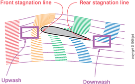
This picture provides some insight into the phenomena known as “upwash” and “downwash”.
If you look at the flow pattern near a wing, e.g. as shown in figure 6, you can see the upwash and downwash. This is discussed at length in reference 1. This flow pattern is induced by the bound vortex; the other vortex segments are so far away that their contribution is not visible in this picture.
This leads to all sorts of questions about how to reconcile the existence of upwash with the notion that the "ambient" air far ahead of the wing did not have any initial upward velocity.
The resolution requires considering the entire column of air a foot or so ahead of the wing. It has no net upward momentum. Yes, there is upwash near the wing, because of the bound vortex ... but there is also downward motion farther above and below the wing, because of the starting vortex. (The bound vortex is nearer, so you might think it would make the dominant contribution, but the angle is wrong; far above the wing, the bound vortex is making mainly a horizontal contribution to the local flow, so it cannot cancel the downward contribution from the starting vortex.)
This point is not widely understood, perhaps because you never see the downward contribution unless you look in the "far field", very far above or below the wing.
Also, as a point of terminology, the terms upwash and downwash generally apply to the contribution of the bound vortex alone. We can say that the "net column momentum" is zero, but there is no such thing as "net upwash". The upwash per se is always nonzero, but it is not the only contribution to the column momentum.
It is important to be able to discuss the distinction between the upwash (due to the bound vortex) as opposed to the total column momentum. The reason is that when the wing moves, the bound vortex moves with it, while the starting vortex does not.
This is what produces lift: the motion of the wing converts some upwashing air into some downwashing air. This results in an increase in the downward momentum of the air, and imparts upward momentum to the airplane. Momentum per unit time is force, and this is the force that supports the weight of the airplane.
We now investigate what happens to this momentum that is imparted to the air.
According to the approximate description given so far, the momentum just flows off to infinity. In an artificial world with an infinitely-thick atmosphere and other suitable boundary conditions, we could just accept that description and go home. But in the real world, we need to enforce the boundary condition that no air flows through the surface of the earth.
The easiest way to do that is by the method of images. The following picture shows a plane that took off from a low altitude and climbed to a higher altitude. By imagining mirror-image vortices below the earth’s surface, we can easily construct a flow field that has zero velocity at the surface.
Of course there are not really vortices under the earth; the point is that when the real air molecules bounce off the real surface they create a velocity field and a pressure field just like what would have been created by the images.
         _ _ > _ _
       /           \
           __>__
     /    /     \    \                           _ _ < _ _
         /       \                             /           \
   |    |    O    |    |                           __<__
         \       /                           /    /     \    \
     \    \__<__/    /                           /       \
                                           |    |    O    |    |
       \ _ _ < _ _ /                             \       /
                                             \    \__>__/    /
           bound
           vortex                              \ _ _ > _ _ /

                                                  starting
                                                   vortex


  ==/\== ==/\== ==/\== ==/\== ==/\== ==/\== ==/\== ==/\== ==/\== boundary

                                                  image of
                                                  starting
                                                   vortex
          image of                               _ _ > _ _
           bound                               /           \
           vortex                                  __>_
         _ _ < _ _                           /    /     \    \
       /           \                             /       \
           __<__                           |    |    O    |    |
     /    /     \    \                           \       /
         /       \                           \    \__<__/    /
   |    |    O    |    |
         \       /                             \ _ _ < _ _ /
     \    \__>__/    /

       \ _ _ > _ _ /
This is how earth recaptures the momentum that the wing imparts to the air. If you include the contribution of the images as well as the real vortices, the total column momentum is zero in every column. The momentum flows as follows:
The momentum that the airplane imparts to the air does not just accumulate in the air.
Finally, let’s check on the energy.
A pair of long vortex segments, such as shown in cross-section in figure 4, has an energy proportional to the length of the segments, and proportional to the logarithm of the separation between the segments1. If the segments are short compared to the distance between them, the energy is essentially independent of that distance.
For each mile that the airplane flies along its flight path, each wingtip needs to make another mile of trailing vortex. This means that flight requires a certain energy per unit length. We call this the induced drag force.
Another way to look at this phenomenon is to multiply the force by the airspeed. This tells us the power (energy per unit time) needed to overcome induced drag. When the airplane is flying slowly, this contributes more to the power budget than friction or anything else.
The energy of the bound vortex segment and the starting vortex segment is constant. The wing does not need to make this energy more than once; it just carries the energy along during flight. Therefore those segments contribute nothing to the power budget.
A surprising number of people try to calculate the magnitude of induced drag merely by looking at the upwash and downwash. This is tantamount to considering the contribution of the bound vortex segment alone, ignoring the other three segments.
We saw in a section 2 that concerning the momentum ahead of the wing, a single-segment analysis predicted infinity when the right answer was zero. It is hard to imagine anything more wrong than that.
Now we are concerned with the energy. The single-segment analysis is “only” 100% wrong, not infinitely wrong.
There is considerable energy in the upwash and downwash, but you should not imagine that the wing must re-create this energy as it flies along. If you have played with vortices in a tub of water, you know
Large vortices in the air, such as hurricanes, can survive for days even after they come ashore and are cut off from their energy inputs. The vortices created by airplanes survive for many minutes. I once flew a 4-seat airplane through the wake of a C5-A that had passed a couple of minutes earlier, and it was quite a memorable experience.
In an established vortex, the same energy rotates around and around and around. This concept, applied to the bound vortex, explains why airplanes can fly with remarkably little drag. Everywhere except near the wingtips, the energy sucked up in the upwash is the same energy that was sent out in the downwash. It gets recycled over and over again.
Another piece of wrong physics that people sometimes do consists of three steps. For a typical section of wing,
This approach might be called the “dimensional analysis” approach. It’s a good illustration of the power, and the limitations, of dimensional analysis, as discussed in section 8. It wouldn’t be too bad if they used a good guess for the mass. The problem is, by looking at the airflow near the wing, you cannot tell how much mass is involved in sharing the momentum.
The only way to get the right answer is to consider the trailing vortices, as discussed in section 6.1.
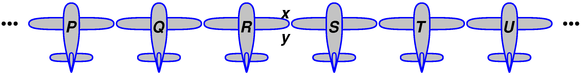
To drive home this point, consider a group of N airplanes flying in formation, wingtip to wingtip, as shown in figure 8.
The left wingtip of the leftmost airplane produces a trailing vortex. Similarly, the right wingtip of the rightmost airplane produces a trailing vortex. The other 2N−2 vortices cancel in pairs. It’s like having a single wing that is N times longer and supporting N times the weight of a single airplane. It produces an amount of lift proportional to N, but the energy per unit length (i.e. induced drag force) in the trailing vortex segments grows only logarithmically with N. The logarithm grows so slowly that it can be considered constant. So the drag of the N-airplane formation is the same as the drag of a single airplane. The N−2 airplanes in the middle of the formation incur practically no induced drag at all.
Many people consider this result non-obvious. Indeed some of them use stronger language, calling it implausible or impossible. Some of them get even nastier than that. But it doesn’t matter. The result is true.
Physically here’s what’s happening: near the trailing vortex line, most of the momentum resides in a small mass of fast-moving air. There’s lots of kinetic energy there. On the other hand, as we move toward the center of the formation, most of the momentum is distributed over a much taller column of air. The column momentum is the same, but the column energy is much less, because the P2 is divided by a larger mass.
Therefore if you want to use the dimensional analysis approach, you must account for the fact that the wing affects the air for a huge distance above and below. This distance is not determined by the chord of the wing, or even by the span of an individual airplane – it is determined by the total span of the whole N-airplane formation.
Dimensional analysis works when applied to the correct physical picture, as discussed section 8.
If you think of the air molecules as a bunch of independent bullets hitting the wing, you will never understand why the drag of a particular airplane depends so strongly on what the other N−1 airplanes are doing. So get used to it: the air is not a bunch of bullets; the air is a fluid, with pressure and velocity everywhere. For more on this, you can refer to reference 1 .
A fluid supports vortices, and a vortex can induce a significant velocity quite far away.
At this point you may be saying, OK, so there is energy per unit length in the trailing vortex — but how does that translate into a force … and how is that force connected to the wing?
The answer is a bit tricky. One ingredient is this: Remember, it is mathematically impossible for a vortex line to have loose ends. Therefore, when we say that there is a vortex line trailing backwards from the right wingtip, it is equivalent to saying that the vortex line is not continuing farther to the right.
Let’s look at point x, which is just ahead of the right wingtip of airplane R in figure 8. During formation flight, half of the upwash at this point is induced by vortex lines to the left of that point, and half is induced by vortex lines the right of that point. The easiest way to understand that “half” is the right answer is by a symmetry argument. You can also obtain the answer quantitatively using the Biot-Savart law, or whatever.
Starting from the large formation shown in figure 8, let’s see what happens in a small formation, created by the departure of airplanes S, T, U, …, and all other airplanes to the right of point x.
Remember that vortex lines are endless. In the large formation, the vortex line extended rightward from aircraft R (continuing as a bound vortex), whereas in the small formation, the vortex line turns a corner and extends to the rear of point y (becoming a trailing vortex).
Interestingly, point y sees essentially just as much downwash in the small formation as it did in the large formation. What it obtained from the rightward half of the bound vortex in the large formation it obtains from the trailing vortex in the small formation.
In contrast, the upwash story is very different. In the small formation, point x is not in a position to receive upwash from the trailing vortex. That means it now has only half as much upwash velocity as it had in the large formation. Point x sees contributions from the bound vortex line, but in the small formation there’s only half as much bound vortex line.
As always, upwash is a good thing. Upwash doesn’t cause drag – it is the lack of upwash that is associated with drag production.
From the pilot’s point of view, the lack of upwash looks the same as a downdraft. The pilot will need to raise the pitch angle and raise the angle of attack to compensate. This will contribute a rearward component to the aerodynamic force. This contribution is called, by definition, the induced drag.
We obtained the same result by means of an energy argument in section 6. So we have two different ways of looking at the same thing. As usual, the energy argument is simple and tells you what must happen, while the force analysis gives a more detailed picture of how it happens.
To summarize this section: Whenever an aircraft is producing trailing vortices – whenever it is producing lift and is not in the interior of a formation – it spends all its time climbing into a downdraft of its own making.
I love qualitative reasoning in general, and dimensional analysis in particular. On several memorable occasions, I have used dimensional analysis to solve some pretty scary problems.
If you see a formula that is dimensionally wrong, you know the physics is totally wrong. But the converse does not hold; if you see a formula that is dimensionally correct, you must not assume that the physics is correct.
Some people think dimensional analysis is magic. If so, it is the sort of magic that can cause trouble for a sorcerer’s apprentice who tries to do too much with it. If you know the physics, dimensional analysis will give you an equation. If you don’t know the physics, dimensional analysis won’t give you the physics or anything else.
In the case of lift production, it is true and obvious that the wing imparts momentum to the air. It is true and obvious that there must be some kinetic energy, P2 / 2M, associated with it. But who would have guessed that almost all the P2 / 2M is near the wingtips?
If you think in terms of vortices, you can use dimensional analysis to get the formula for induced drag, as follows:
The velocity induced by a single vortex segment falls off like 1/r. The energy depends on velocity squared, so it falls off like 1/r squared. We must integrate this in cylindrical coordinates, using the measure r dr dθ dz. That means the integrand goes like 1/r, and the integral goes like log(r). That’s a bad thing, since it diverges at both the upper and lower limits of integration. So we need to look for some cutoff factors. For large r, the cutoff occurs because the field of the left trailing vortex cancels the field of the right trailing vortex. This occurs when r is large compared to b, the separation between the vortices. So the energy must go like log(b/a), where a denotes the size of the vortex core. The eye of a hurricane is an example of a vortex core. It does not participate in the 1/r velocity profile. You can think of this region as undergoing uniform cylinder-like rotation (velocity proportional to r, not 1/r). Once we realize that the core is nonsingular, the details aren’t very interesting, because the core is small. We can guess a value for the core-size, and the guess doesn’t need to be very accurate, since it affects the final answer only logarithmically. So our final dimensional-analysis result is that the energy goes like z*log(b/a), which is very nearly the right answer.
If you want to compare this with a full-blown calculation, you can look at reference 5 page 78, which gives z*(0.25 + log(b/a)) — so it looks like we came as close as possible, within the limits of dimensional analysis.
Copyright © 2007 jsd