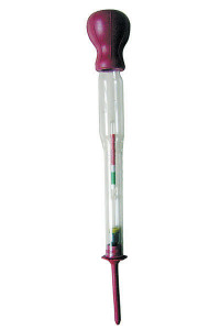
Figure 1: Simple Hydrometer
The factory makes each cell in the battery as follows: Connected to the “−” terminal is a thick, porous plate of metallic lead. Connected to the “+” terminal is a plate consisting mostly of porous lead dioxide paste, supported on a thin metal grid. In between the plates is fairly concentrated sulfuric acid (about 4M).
By way of preliminaries, we note that sulfuric acid is a strong acid with respect to its first proton, so even before the acid has been added to the battery, the following reaction has gone to completion:
| (1) |
This reaction is associated with the bulk electrolyte, independent of the plates of the battery. It is not an electrochemical reaction and is independent of the charging and discharging of the battery. We do not expect sulfuric acid to release its its second proton with any great likelihood – only a fraction of a percent – since Ka2 is only 0.012.
As the battery discharges, the following half-cell reaction takes place at the “−” plate:
| (2) |
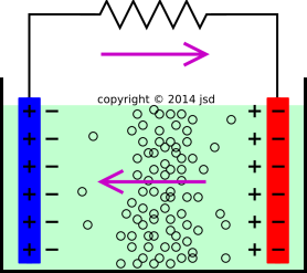
This reaction makes a lot of sense. As discussed in reference 1, when the cell is under load, there is an electric field in the electrolyte that causes negative ions (in this case bisulfate) to drift toward the “−” plate. See figure 2. The negative ion is consumed by reacting with the plate. The reaction also produces a positive ion (proton) which drifts away under the influence of the aformentioned field. Two electrons are left behind in the plate, to be delivered to the terminal. There’s nothing surprising about any of that.
The “forward” direction of equation 2 represents discharging the battery. To represent the charging (aka recharging) operation, just reverse the direction of the arrow. The result makes sense, too.
Meanwhile, the other half of the discharge reaction takes place at the “+” plate. This can be written in various ways, of which the following is conventional:
| (3) |
Some details of equation 3 require extra-careful analysis, as will be discussed in section 2 and section 3. First, however, let’s discuss a few things are relatively easy to understand.
At each plate, the lead compounds are insoluble and stay attached to the plate; there is never any significant amount of lead in solution. The other reaction products (water and sulfuric acid) are completely soluble. These properties are an important part of why the cell is rechargeable. (In contrast, in non-rechargeable batteries, there are typically reaction products that become unavailable for re-use, departing as a gas or as an insoluble precipitate.)
Similarly, the free electrons that are liberated by equation 2 and consumed by equation 3 are not soluble in the electrolyte. The ions H+ and HSO4− are soluble, but the electrons are not. This may seem obvious, but it is not trivial. If electrons were soluble, the battery would not work. It would short itself out.
If we add the two half-cell reactions together, we get the full-cell discharge reaction:
| (4) |
During the discharge operation, acid is consumed and water is produced. During the charge operation, water is consumed and acid is produced. Because sulfuric acid is much denser than water, a widely-used technique for checking the state-of-charge of a battery is to measure the specific gravity of the electrolyte. (Non-experts sometimes guess that the change in density is due to the presence of heavy lead compounds in solution, as if some sort of lead-plating reaction were involved, but this is not the case.) See figure 1.
During discharge, at the “−” plate, the lead is oxidized from metallic Pb to divalent Pb(II). This liberates negative charge into the “−” plate. Meanwhile, at the “+” plate, the lead is reduced from tetravalent Pb(IV) to divalent Pb(II). This liberates positive charge into the “+” plate.
Of course during recharge, the opposite redox reactions occur.
Beware of some tricky terminology:
The situation is summarized in the following table:
| charging | discharging | |||
| − plate: | cathode being reduced | anode being oxidized | ||
| + plate: | anode being oxidized | cathode being reduced |
From this we can conclude that for a rechargeable battery, you should never mark the words “cathode” or “anode” on the terminals. See reference 2 for a proper definition of “anode” and “cathode”, along with related issues.
By way of background, consider heterogeneous catalysis, such as the catalytic oxidation of acetone vapor on a copper surface. If there is no stirring, the reaction will proceed only slowly, because the reactants need to diffuse to the surface, and the products need to diffuse away. Diffusion is a rather slow process, especially diffusion over long distances.
Note that this picture of reactants (or products) flowing along a concentration gradient is inconsistent with your intuition about the flow of electric current in a DC circuit. Consider the following contrast:
| Chemical Reaction | DC Circuit |
| The reactants and products are not indestructible. The reactants are depleted during the reaction. The products accumulate. | The charge flows like an incompressible, indestructible fluid, with no accumulation or depletion anywhere. |
Note that in a lead-acid battery, during discharge, bisulfate ions are consumed at both places, both at the “−” plate and at the “+” plate, as indicated in equation 2 and equation 3. During discharge the electrolyte becomes significantly more dilute, as bisulfate is consumed and water is liberated. One practical consequence is that you can measure how fully charged the battery is by measuring the density of the electrolyte using a hydrometer, perhaps of the simple kind shown in figure 1.
First consider open-circuit, zero-load, equilibrium conditions. There is no electric field in the bulk of the electrolyte. This stands to reason. If there were an electric field, the ions would be driven by the field. The positive ions would flow in one direction and the negative ions would flow in the other direction, contradicting the assumption that this is a zero-current equilibrium situation.
Also, in equilibrium there is no significant concentration gradient in the bulk of the electrolyte.
Now consider the discharge operation, as shown in figure 2. The blue plate is the “+” plate, and the red plate is the “−” plate. The purple arrows show the direction of current flow. They also show the direction of the electric field. It is energetically favorable for positive charge to flow in the direction of the arrows.
By the same token, it is energetically favorable for negative species to flow in the direction opposite to the arrows. In particular, this means that bisufate ions will be driven left-to-right in figure 2, providing a supply of reactants as required by equation 2. So far so good.
Alas we cannot use this line of reasoning to explain how bisulfate ions get to the positive terminal. Equation 3 will soon consume all the bisulfate ions in the immediate vicinity. If the reaction is to continue, these need to be replenished from somewhere. This requires ions to to flow uphill (against the gradient of the electrochemical potential).
The only possible explanation is that some of the ions diffuse uphill. This is certainly possible, given the very large concentrations and short distances involved. The distribution of small black circles in figure 2 is meant to be a highly exaggerated represention of the concentration of bisulfate anions. Diffusion will cause the anions to flow from the bulk toward the plates, in both directions.
Let’s be clear: At the “−” plate life is simple, because drift and diffusion are working together to bring reactants toward the plate. In contrast, the situation at the “+” terminal is a mess, because drift is working in the unhelpful direction, and we have to rely on diffusion to bring reactants to the plate. This is much worse than the acetone reaction considered in section 2.1, where the diffusion was unopposed.
It is easy to conjecture that whatever is going on near the positive plate poses a significant limitation on how much current we can get out of the battery. We can also predict that stirring the electrolyte will increase battery performance. Lots of stirring schemes are discussed in the literature, but usually only at a phenomenological, non-detailed level.
It is hard to find quantitative details about whatever microscopic processes are going on in the electrolyte in the vicinity of the “+” plate. A standard book on lead-acid batteries is reference 3, but it doesn’t delve into this issue. Some tantalizing web pages are reference 4 and reference 5. If anybody knows any good references on this subject, please let me know.
Let’s put in some numbers: The cell has an open-circuit voltage of 2.2 volts are so. Suppose that we put it under heavy load, so that there is Δv = 0.4 volts “IR” drop across the electrolyte. As always, room temperature corresponds to 25 meV, i.e. .025 electron-volts. We can use that to calculate the Boltzmann factor, i.e. the fraction of the bisulfate ions manage to climb the potential is exp(q Δv / kT) = exp(.4 / .025) = 9,000,000. So under high-current conditions, if the reaction is rate-limited by the availability of bisulfate ions, we expect the reaction at the “+” plate to proceed millions of times slower than it “ideally” would.
In contrast, under low-current conditions, the reaction is rate-limited by the availability of electrons, so the availability of bisulfate ions is not an issue.
In the foregoing calculation, we ignored the effect of dielectric screening. This may or may not have been the right thing. Argument pro: energy is conserved. At the end of the day, to move a bisulfate ion up a hill 0.4 volts high, you have to do 0.4 eV of work. Argument con: most of the height of the hill is associated with the dipole layer at the edge of the water, at the place where the electrolyte meets the plate; within the bulk of the electrolyte the field is smaller. The ions can with relatively resonable probability get close to the “+” plate, just outside the dipole layer. Unanswered question: if they get that close, is that close enough?
In any case, screening does not completely eliminate the energy barrier. By the usual Clausius-Mossotti argument (reference 6), the field inside a spherical hole in a dielectric is 1/3rd of the way between the fully-screened value and the unscreened value. So if we put in the numbers, we get the cube root of the previous number, i.e. a factor of 200. That’s a lot less than 9 million, but it’s still big enough to be worth paying attention to. I conjecture that it limits the amount of current that the battery can put out.
Is the reaction really third order in proton concentration, as suggested by equation 3? I doubt it. I suspect this would give the battery a very peculiar I−V characteristic, unlike what is observed.
If the reaction proceeds via some sequence of intermediate steps, perhaps along the lines of the hypothetical reactions given in this section, there would be a lower-order dependence on H+ activity.
Here is a possible sequence:
|
As discussed in section 2, it is energetically unfavorable for the bisulfate anions to move toward the positive plate, which is limitation on equation 5c. In contrast, no such limitation applies to the OH− anions in equation 5d, because they are being produced at the positive plate. They don’t need to move toward the plate. It is energetically favorable for H+ ions to drift toward the positive plate.
In terms of charge, the net effect of equation 5 is that two electrons are transferrred from the plate into the electrolyte, so that two units of positive charge are delivered to the terminal.
Here’s another hypothetical sequence, using PbO instead of Pb(OH)2 as the intermediate:
|
I have no data on whether any of the hypothetical reactions listed above play any role in real batteries.