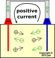
Figure 1: Simple Model: Battery Being Discharged
On any battery, one terminal is labeled positive (+) while the other is labeled negative (−). The labels are based on voltage, such that the positive terminal is at a higher voltage than the negative terminal. Voltage is defined as energy per unit charge, as discussed in reference 1.
When the battery is being discharged, positive current comes out of the positive terminal. When viewed from outside the battery, this makes perfect sense; positive charge can lower its potential energy by moving away from the higher-voltage region.
However ... if we think about the internals, something tricky must be happening. Positive charge must be transported through the battery, internally, towards the positive terminal. Positive charge must be transported uphill to the positive terminal.
This is possible because ... wait for it ... chemistry happens.
Every chemical reaction has to be balanced with respect to each species of atom involved ... and also balanced with respect to charge. In the battery, there is a reaction that cannot proceed unless some charge is transferred. By the same token, the charge cannot be transferred unless the reaction proceeds. The two are linked. The reaction provides the energy needed to move the charge uphill.
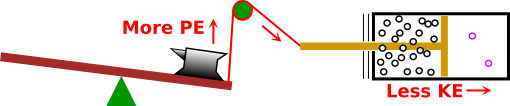
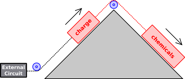
Figure 1 is a useful metaphor for what is going on. During discharge, the chemicals move to a lower energy state. In so doing, they drag some charge to a higher energy state. In this metaphor, the red rope represents the physics that links the charge to the other chemical processes.
The external circuit controls the rate at which charge flows in the system. If the external circuit is a dead short, the reaction proceeds to completion, very quickly.
It must be emphasized that when you get energy out of a battery, the energy does not miraculously appear out of nowhere. The energy comes from chemical reactions within the battery. During discharge, the reaction proceeds, consuming reactants, producing products, and liberating energy.
For a rechargeable battery, when it is being charged, the charge within the battery moves downhill, dragging the chemicals uphill to a higher-energy state. This is opposite to the direction indicated by the black arrows in figure 1.
Beware that the “up” direction in figure 1 represents energy in the most vague, abstract sense. It includes all forms of energy, not just electrostatic potential energy. This is relevant for reasons discussed in section 1.2.
If you are happy with the model presented in section 1.1, feel free to skip this section.
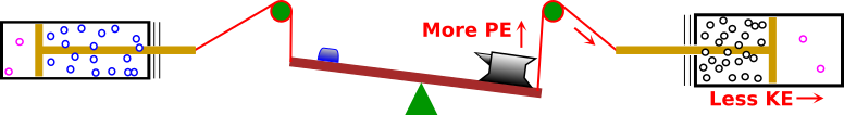
However, if you would like a model that captures what’s going on in somewhat more detail, take a look at figure 3.
Near the right side the diagram, we have some gas pushing on a piston. All of the energy within the gas consists of kinetic energy. As the gas expands, it moves to a state with lower kinetic energy.
The piston is connected to a rope (shown in red) that goes over a pulley. The only way the gas can expand is if the anvil goes up. This increases the gravitational potential energy.
This is analogous to electrochemistry in the following sense: The energy of the electrons in an atom contains contributions from the kinetic energy, plus contributions from the electrostatic potential. In the atom these are inseparable, since both are properties of the electron cloud. In figure 3 we separate them, so the kinetic energy is represented by the gas molecules (black circles) while the potential energy is represented by the anvil.
Figure 3 shows a more complete model. When a battery is being discharged, multiple chemical reactions occur. Some electrons move into states of lower kinetic energy, as represented by the anvil. This contributes to driving the reaction forward. Meanwhile other electrons move into states of higher potential energy, as represented by the blue blob on the left side of the teeter totter.
Similar words apply to the kinetic energy. The left side of the diagram represents an object with smaller mass (blue blob) and also smaller kinetic energy (smaller piston, with fewer blue circles).
Tangential remark: The potential energy of the anvil is a linear function of height above the ground, but it is a nonlinear function of how much rope is payed out, because there are mechanical-advantage issues. Also the pressure behind the piston is a nonlinear function of the position. Analogous nonlinearities exist in an atom, and are important, because they allow the system to find an equilibrium. (If everything were completely linear, the system would exhibit “winner take all” runaway behavior. That is, if the anvil started going down it would go down forever.)
As always, the KE and PE are linked by the laws of quantum mechanics. The KE depends on the curvature of the wavefunction, and the PE depends on where the wavfunction sits relative to the atomic nucleus.
Correct operation of a battery depends on a great many details, including the following. (You can skip these details if you want.)
Even though a battery may look simple, the inner workings are complicated. It is not possible to explain everything at once, so we will use a process of successive refinement, using progressively better approximations.
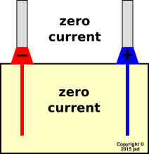
We start by considering a battery at rest. By that we mean that the terminals are open-circuited, as shown in figure 4. Since there is no current flowing outside the battery, ideally there is no current flowing inside the battery either. More specifically, conservation of charge (aka continuity of current) tells us there must be zero net current. (As we shall see, zero net current is not the same as zero current.)
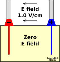
We choose a battery that puts out 1.5 volts at rest, with terminals 1.5 cm apart, in the geometry shown in figure 5. This implies that there is an electric field of 1.0 V/cm between the terminals. If there is no current in the electrolyte within the battery, there will be no E field there either. We can explain that as follows: The electrolyte (by definition) is loaded with ions. Whenever there is an electric field, the ions drift around. They keep drifting until they run into a surface that stops them. This process continues until the accumulated ions on the surface create a field that cancels whatever field we started with, resulting in zero net field in the bulk. By “bulk” we mean everywhere except right near the boundaries. (The situation near the boundaries is a mess, which we are not going to worry about right now.)
It must be emphasized that figure 5 embodies a number of idealizations, and leaves out several important details. For example, the astute reader will have noticed that the field in figure 5 appears to have a tremendous amount of curl ... which is not consistent with the Maxwell equations at DC. To say the same thing another way, it is not obvious how to draw the electric potential contours in such a diagram. The answer is that there are some tremendously strong fields at the boundaries, e.g. where the electrolyte touches the electrodes. A tremendous number of contour lines are bunched up near the boundaries. We are not going to worry about this at the moment. Let’s concentrate on what’s going on in the bulk, far from the boundaries.
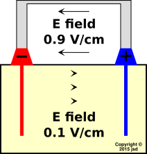
We now shift attention the situation where where the battery is being discharged via a thin, high-resistance wire connected across the terminals, as shown in figure 6. We choose a load that causes the terminal voltage to be about 10% less than the open-circuit voltage. In the diagram, positive conventional current is flowing right-to-left in the resistance wire. At the microscopic level, we know the current is carried by electrons, which are flowing left-to-right.
If we look inside the dielectric, we find that the current is being carried by ions. Conservation of charge (aka continuity of current) tells us that on average there must be positive ions flowing left-to-right and/or negative ions flowing right-to-left (or some of each).
To a first approximation, the electric field of a battery under load is related to the electric field at rest in a remarkably simple way. Starting with the fields shown in figure 5, add a small uniform left-to-right field everywhere; this produces the fields shown in figure 7. In the bulk electrolyte, the small additional field adds to the prior zero to produce a net left-to-right field. Outside, between the terminals, the additional field opposes the prior field to produce a slightly smaler right-to-left field. We can explain this by saying that to a first approximation, the voltage across the boundary layer stays the same. That is, the complicated electrochemistry at the boundary between the electrolyte and the electrode stays the same.
The direction of the field in the electrolyte is plausible, insofar as the field in figure 7 is consistent with the direction of ion drift shown in figure 6. The electric force on the postitive ions is left-to-right, and they drift left-to-right; the electric force on the negative ions is right-to-left, and they drift right-to-left.
|
| |
| Figure 6: Current :: Ideal Battery During Discharge | Figure 7: E Field :: Ideal Battery During Discharge | |
Before we go on, here’s a reminder about how science is done: As Galileo pointed out on Day One of modern science: We depend on the laws of physics to describe what happens. They may or may not explain how it happens. The fundamental laws rarely if ever explain why it happens.
In this section, we have given an approximate description of the fields and currents, without attempting to give a microscopic explanation of how these fields and currents come about. For example, based on macroscopic observations plus conservation of charge, we know that the ions must (on average!) flow in the direction depicted in figure 6. This is somewhat useful, even though it doesn’t tell us much about the microscopic mechanisms.
Sometimes when looking at a diagram, people assume that everything that is shown is important, and everything that is not shown is unimportant. Well, that is definitely not a safe assumption in figure 7. Some of the electric fields are shown, but some are not ... and the fields that are not shown are actually quite important.
We have presented a plausible example of what could be happening inside a battery. However, it must be emphasized that an example is not a proof ... and plausibility is not a proof either. In reality, some batteries work pretty much as described here, but some of them don’t. By way of counterexample, in a lead-acid storage battery during discharge, some of the bisulfate ions move in the direction shown in figure 6, but some of them don’t. Some of them move uphill, against the electric field. This doesn’t violate conservation of charge, because for every ion that moves the wrong way, a larger number of ions move the right way. So figure 6 is correct “on average” but not necessarily correct in detail.
This brings us to another fundamental principle of physics: Force is not motion. Although there are certain situations motion will always be in the same direction of force, this is not the general rule. There are a lot of ways it could go wrong. For example, if you open a bottle of perfume and set it on the floor, the perfume molecules will eventually diffuse throughout the room, from floor to ceiling, even though the molecules are very much heavier than air. In general there is a competition between drift (in the direction of the force) and diffusion (in the direction of the concentration gradient).
In grade school you were probably taught about the importance of stability, which they explained in terms of energy. This is required by the Next Generation Science Standards. The only problem is, it’s not true. The perfume molecules obviously do not settle into the lowest-energy state. Not even close. Neither do the air molecules, for that matter. Don’t believe everything you read in grade-school science books. In reality, the distribution of molecules is governed more by entropy than by energy. Sometimes minimum energy serves as a proxy for maximum entropy ... but sometimes it doesn’t.
The idea of work function is central to any understanding of electrochemistry, including contact electrification (aka static electricity) as well as batteries, fuel cells, electroplating, et cetera. Please make sure you are familiar with the ideas in reference 2 before continuing with this document.
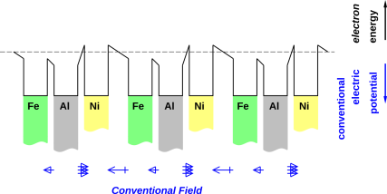
Consider the arrangement of metal chunks shown in figure 8. This was introduced and explained in reference 2.
We can convert these isolated metal chunks into a battery by putting an electrolyte in the gaps between the nickel and the iron. Let’s use potassium hydroxide for the electrolyte. We keep the iron electrode from the discussion above. Rather than using a plain nickel electrode, we use nickel coated with nickel oxyhydroxide, NiOOH, because that gives us a nice rechargeable cell.
A good electrolyte has several interesting properties; for one thing it has lots of ion-pairs in it. When we put an ion-pair in an electrical field, such as in the Ni-Fe gap, the positive ion will tend to drift one way and the negative ion will tend to drift the other way. This process will continue until the electrochemical field in the interior of the gap becomes a constant, independent of position, which is the equilibrium condition. There could be some electrical potential gradient; I don’t think there is much but there could be some. And there could be some concentration gradient; again I don’t think there is much, but there could be some. In any case, when you consider the concentration gradient and the electrical gradient together, in equilibrium there is no net motion of ions. In the simplest case, there is no electrical field (hence no drift) and no concentration gradient (hence no net diffusion). In the more general case, drift due to the electrical potential gradient is counterbalanced by diffusion along the concentration gradient. The two gradients point in opposite direction, and when we add the two effects (electrical and concentration) we find that the electrochemical potential has zero gradient.
All that applies to the interior of the gaps, in the bulk electrolyte. At the ends of each gap, there will, in general, be some accumulation of ions. This produces a complicated dipole layer (aka bilayer) there. The strength of the dipole layer depends on the properties of the electrolyte, as well as on the properties of the adjacent metal, as discussed in section 2.4. The strength of the dipole layer determines how the potential in the interior of the gap is related to the potential in the interior of the adjacent metal. For more about the importance of dipole layers, see reference 3.
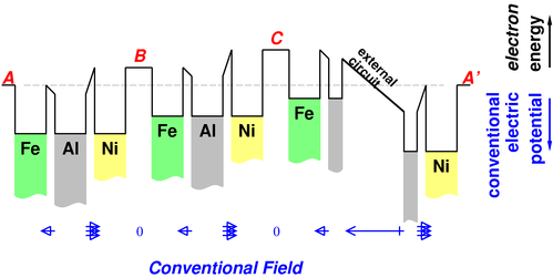
The result is shown in figure 9.
In the previous case, when we had electron-equilibrium as shown in figure 8, the potential difference due to the work-function difference was undone by the field in the gaps; now, with electrolyte in the gaps, the gaps are field-free except in the boundary layers. Note that the potential in the gap at A′ lines up with the potential in the gap at A, as it should, since A and A′ represent the same point (since we have periodic boundary conditions), and the gap at A≡A′ is one of the field-free electrolyte-filled regions.
This situation does not represent electron-equilibrium everywhere; the ions in the gaps establish a field-free region in the interior of each gap, which is not the equilibrium condition.
Let’s cut the aluminum wire between cell C and cell A′ and insert a voltmeter there, at the location marked “external circuit” figure 9.
Each cell is like a step on a staircase. An electron in the leftmost Fe electrode has less energy than an electron in the next Fe electrode, which in turn has less energy than an electron in the rightmost Fe electrode. You wind up with a substantial voltage indicated on the voltmeter.
We can figure out the sign of the voltage from figure 9. Electrons are more unhappy just to the left of the external circuit than they are just to the right of it. So somebody outside the battery, treating the battery as a two-terminal black box, will see electrons trying to leave via the Fe terminal, flow through the external circuitry (including the voltmeter) and thence enter the Ni terminal. The Fe terminal is therefore appropriately labeled the "-" terminal. Naturally the Ni terminal is appropriately labeled the "+" terminal.
Here’s one essential piece of the magic: running a wire between a piece of Fe and a piece of Ni is very different from putting some reactive ionic electrolyte between them. If you read the diagram from left to right you get
Fe-Al-Ni-electrolyte-Fe-Al-Ni-electrolyte
which is not a palindrome. There is a definite direction to the structure, and that determines which end of the battery is positive and which is negative. If you replaced the electrolyte with an aluminum wire, you would get a palindrome, which couldn’t possibly produce a useful voltage.
Work functions are part of the story, but not the whole story. The work functions measure the energy required to take an electron out of the metal into the vacuum. This is not quite what’s happening in the battery; there are chemical reactions taking place that change the energy budget. This is discussed in section 2.3 and especially section 2.4.
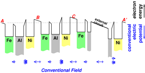
In figure 9. the battery is open-circuited, so no current of any kind is flowing anywhere. But if we attach an electrical load to the terminals of the battery, the voltage-difference across the terminals sags a bit, as shown in figure 10.
In this case, the electrolyte-filled gaps are no longer field-free. The electrolyte carries a current, but it is not a current of electrons, but rather a current of drifting ions. (There may also be some leakage of electrons, but this is an unimportant nuisance effect.) Ion-pairs are pulled apart by the field. Positive ions drift left, and negative ions drift right. The positive ions are neutralized by electrons that come out of the Ni electrode; the negative ions are neutralized by donating an electron to the Fe electrode. The result is a steady flow of negative electrical current from left to right, or to say it the other way, a steady flow of conventional positive current from right to left.
It is important that electrons (and not ions) can move through the aluminum wire, while in contrast ions (and not free electrons) can move through the electrolyte.
Consider cell (B). An electron will not naturally flow left-to-right from inside the Ni electrode to the left of point (B) to inside the Fe electrode to the right of that point. An electron that magically appeared in the gap would flow the correct way, left-to-right, but when you take the work functions into account, it would be energetically unfavorable for an electron to hop out of the Ni into the gap. When the battery is in operation, we are not asking any electrons to flow like that. Net negative charge yes, electrons no.
But you may well ask, doesn’t it come to the same thing? Well, not quite, because the electron that comes out of the Ni electrode to neutralize the positive electrolyte ion gets help from the energy of the chemical reaction that takes place on the electrode. The physics goes like this:
The reaction at the Fe electrode does not undo that energy gain, because it is a different reaction. Different chemical species are involved. We say that there are two half-cell reactions. In this case there is a half-cell reaction between the positive ions and the Ni electrode, and a different half-cell reaction between the negative ions and the Fe electrode.
So we see that the energy of the battery comes from the chemical reactions occurring at the surfaces of the electrodes. That’s not a surprise.
For each unit charge that flows through a cell, one unit of chemical reaction takes place at each plate, at the plate/electrolyte boundary. (We are assuming that the electrolyte was 100% ionized to begin with. In accordance with convention, we don’t count the ion-forming reaction.) Without these reactions, the cell would just charge up like a capacitor and the battery would not be effective at maintaining its rated voltage when placed under load. The voltage stays the same (more or less) until you run out of chemicals. (This is how the unit of charge was initially defined: the amount of chemical precipitated in such a cell.)
Section 2.3 mentioned that the energy of the chemical reaction "helped" the electron overcome the work function. We don’t expect the half-cell reaction to have exactly the right energy to match a particular work function, which is why the potential in the gap in figure 9. has a nontrivial relationship to the potential in the adjacent metal. Let’s see how this relationship arises.
Start with the picture in figure 9. where there is no field in the gaps. Then let a current flow through the battery. The gap will charge up like a capacitor. There will develop a field in the gap, roughly as shown in figure 10. The field will cause ions to drift. Positive ions will congregate near the Ni electrode. So far, none of them have been reacted with the electrode, because they haven’t been able to get the necessary electron. The drift will get rid of the field in most of the gap, but there will be a tremendous field right near the electrode, where all the ions are congregating. (The average field in the gap will be unaffected by the drift; it will just be the "capacitor" voltage divided by the gap distance.)
Before long, the concentrated field near the plate will become so strong that the chemical reaction plus this field will provide enough energy to pull an electron up and over (or through) the work function barrier. One unit of chemical reaction will take place.
During discharge, the reaction that takes place at the nickel electrode is:
| (1) |
This reaction is energetically favorable as written. The net energy per electron liberated by this reaction is called the half-cell potential, potential, φ¢ . Typically such potentials are measured in volts. If you are tempted to abbreviate the units, beware that V for volt conflicts with V for vanadium. This can be a problem when typing reaction equations into a computer, which might be unduly literal-minded about such things.
We recognize equation 1 a reduction reaction because it has free electrons on the reactant side of the equation. Since it is a reduction reaction, the half-cell potential is also called a reduction potential, φred= φ¢ .
The sign of the half-cell potential is such that φ¢ is the energy per electron that must be added to the product side of the equation to balance the equation. If you ever forget this fact, look at the table of reduction potentials (reference 4) and find the entry for the reduction of Na+. You know the reverse reaction is spectacularly violent, so you know the reaction as written – the reduction reaction – is energetically unfavorable. This reaction has a negative reduction potential. This should be a sufficient reminder of how to interpret the sign of the reduction potential.
Meanwhile, as part of the same discharge process, another half-cell reaction is taking place at the other electrode:
| (2) |
This reaction is energetically favorable as written.
We recognize equation 2 an oxidation reaction because it has free electrons on the product side of the equation. Since it is an oxidation reaction, the half-cell potential is the negative of the reduction potential: φred= −φ¢ .
A large table of half-cell reactions and the associated reduction potentials can be found in reference 4.
Note that it is conventional to talk about reduction potentials (not “oxidation potentials”). You could define a “oxidation potential” if you wanted, but it’s usually not worth the trouble. For oxidation reactions, usually easier to just use the negative of the reduction potential.
The overall reaction in the cell consists of two copies of equation 1 plus one copy of equation 2, for a total of:
You should never be in too much of a hurry to write the full-cell reaction equation. It is significantly less informative than the two half-cell reaction equations separately. Although we show the magnitude of the potential in equation 3b, we cannot determine the sign or magnitude of this quantity by looking at the chemistry in equation 3a alone.
In contrast, if we look behind the scenes, referring back to the two half-cell reactions, we find:
A volt is defined to be one joule per colomb. The charge on an electron is 1.60218×10⁻¹⁹ coulombs. The charge on a mole of electrons is therefore 96485.3 colombs. A volt is therefore 96.4853 kilojoules per mole.
Note contrast between the “energy” convention and the “voltage” convention:
| For several very good reasons, the ΔE that appears in equation 3 is the energy per mole of reaction, i.e. per mole of “→” ... not per mole of electrons. This is conventional and practical, because it is consistent with the way we measure reactants and products. | By definition, voltage corresponds to energy per electron. One volt is one eV per electron, or equivalently one joule per coulomb, or 96485.5 joules per mole of electrons. This is conventional and practical, because voltmeters are readily available, and this is what they measure. |
Because equation 2 and equation 3 involve two moles of electrons per mole of “→”, there is an important factor of 2 involved in the conversion between ΔE and φ. Beware.
Many people learn about “chemistry” in one class and learn about “electricity” in another class. That’s unfortunate, to the extent that the connections between the two subjects are not clearly explained.
What’s worse is that many chemistry texts introduce electrochemistry in terms of the “oxidation number” scheme, which is – to put it politely – unnecessarily complicated, unclear, and unreliable. I have never seen any application of the “oxidation number” scheme that could not be handled more conveniently by other methods, as we now discuss.
By way of background: The process of balancing chemical reactions, – i.e. the topic of stoichiometry – can be considered nothing more or less than the application of certain conservation laws. If you are considering 92 different chemical elements, there are 92 different conservation laws, since in chemical reactions each element is separately conserved.1
If you understand stoichiometry, you can understand oxidation-reduction reactions with no additional conceptual effort. You just need to add a 93rd conservation law, namely conservation of charge. Then to write a balanced electrochemical equation, you just need to balance it with respect to atoms and with respect to charge.
Consider the comparison:
| Consider a non-electrochemical reaction, such as the simple reaction of carbon with oxygen to form carbon dioxide. It doesn’t make sense to talk about this reaction except in terms of the balanced reaction equation: C + O2 → CO2. You must account for all the atoms. | The same applies to electrochemical equations, i.e. oxidation-reduction reactions. You must account for all the atoms and account for all the charge. |
| Even if you consider side-reactions, such as the possibility of reacting carbon with oxygen to form carbon monoxide, it doesn’t make sense to talk about the side-reaction except in terms of the balanced reaction equation, C + 0.5 O2 → CO. | In each and every reaction, including side reactions, you must account for all the atoms and account for all the charge. |
For details (including examples) of how to balance reaction equations with respect to atoms and charge, see reference 5. Tangential remark: The idea that reactions must be balanced with respect to atoms and with respect to charge is useful in many contexts, not limited to batteries. For example, it allows you to understand why you can do things with aqua regia that you can’t do with nitric acid or hydrochloric acid separately.
While we’re on the subject: Reactions must be balanced with respect to energy, not just atoms and charge. This three-way linkage of chemistry, charge, and energy is what makes batteries possible. That’s because ultimately, the energy of the battery is the energy of chemical reactions.
In a battery under load, i.e. when it is functioning as a battery, the electric field in almost all of the electrolyte compartment is in the “forward” direction, i.e. the direction that causes any mobile charges to drift in the direction of overall current flow in the circuit. This can be seen in figure 10.
By Kirchhoff’s law, we know that the total voltage drop around the circuit is zero. All of the reverse voltage drops occur within very thin dipole layers. This is also where all of the interesting chemistry takes place. There are tremendously high electrical fields in these regions, and high chemical concentration gradients. Analyzing the details of what goes on in these regions is not easy.
According to a modern microscopic understanding of metals, the relevant electrons (i.e. the ones that give the metal its metallic properties) all have a tremendous amount of kinetic energy. They are zooming around like crazy. If no net current is flowing, it’s because an equal number are zooming in all directions, so the electron wavefunction is a standing wave. If a current is flowing, it’s because of a slight increase in the number zooming to the right and a slight decrease in the number zooming to the left, with no significant change in the kinetic energy.
The amount of such kinetic energy depends on the lattice-spacing in the metal and on the number of electrons, as discussed in reference 2. This is a big contribution to the electrochemical potential.
You may be wondering, which is it: kinetic or potential? If it’s called a potential, how can it be kinetic? The answer is that the defining property of a potential is that it has a value that depends on position, independent of how you got there. The relevant electrons in a metal do in fact have this property: they must have a huge kinetic energy, otherwise they could not exist inside the metal. This energy is independent of how the electrons got there, so it is not wrong to call it a potential. It acts like a potential. In fact, people have been calling it a potential for over a hundred years, since long before anyone could explain it microscopically, in terms of kinetic energy and the exclusion principle.
The full electrochemical potential includes to contributions. In addition to the "chemical" contribution just discussed, there is the plain old electrostatic potential. If you put a net charge on a piece of metal, you change its potential, according to the usual notions of capacitance.
Consider the following contrast:
| Case A: We have two parallel plates, each of which bears a charge Q/2. We could say there is a charge Q “on” the pair of plates. | Case C: Suppose we treat the two plates as a capacitor, with charge +Q on one plate and charge −Q on the other. We could say there is a charge Q “on” the capacitor. |
| Case B:There are innumerable intermediate scenarios. |
This is a problem, because the word “charge” is being used in two inconsistent ways. The is a recipe for disaster, especially when it involves something as fundamental as charge.
I strongly recommend reserving the word “charge” to apply to case A, and using the word “gorge” to apply to case C. Intermediate scenarios involve some combination of charge and gorge. See reference 6 for details.
Using this terminology, we can state with absolute clarity that charge is never created or destroyed.
In contrast, it is easy to create or destroy gorge, by creating pairs of equal-and-opposite charges, by ionizing some previously-neutral chemical. No charge was created, not even temporarily.
We can speak of charge flowing through the cells. In contrast, we should not think of charge flowing “out” of the cells like water pouring out of a bucket. In normal operation, if an electron flows out one terminal, an electron flows in the other terminal at the very same instant. When this happens, the cell accumulates gorge but does not accumulate charge.
In this document, we have discussed several examples of battery chemistry, not including lead-acid batteries. They are obviously very important in practice. They are not, however, easy to understand. See reference 7.
There are some things in physics that can be explained just fine by treating atoms as classical particles. The ideal gas law PV = NRT is often cited as an example. But there are other things that seem just as elementary but cannot be explained in terms of 19th-century physics. The Gibbs "paradox" is an example. It makes sense if you know how quantum mechanics deals with identical particles, and it is severely paradoxical otherwise.
Similarly, there are some parts of chemistry that can be described just fine using ball-and-stick models of atoms and bonds that snap together to make molecules. But there are other things that cannot be understood this way. For starters, if you insist on a strictly 19th-century analysis, atoms are unstable. The electron will spiral in towards the nucleus and the atom will shrink away to nothing. If you insist on a purely classical analysis, there will be no atoms, no molecules, no metals, no work functions, no batteries, and no people around to complain about it.
You need quantum mechanics if you want atoms to even exist. You need more quantum mechanics if you want the various chemical elements to not behave all the same. Without the exclusion principle, helium would behave just like a heavy isotope of hydrogen. And lithium would be the same, only even heavier. And oxygen would be the same again, only heavier still.
If you want to understand where work functions come from and/or where battery voltages come from, you will have to accept the fact that electrons stick to some atoms more than others. You can accept this as an observed fact without explanation, or you can seek an explanation in terms of quantum mechanics.
We live in a world governed by the laws of quantum mechanics. Get used to it. Sometimes there is a ball-and-stick model that provides a passable approximation to the real (quantum) physics; sometimes there isn’t.
“Contact Electrification”
www.av8n.com/physics/workfun.htm