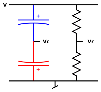
Figure 1: Non-Polarized Capacitor
Question: Will two electrolytics back-to-back work as a non-polarized capacitor?
Answer: Yes. This is standard practice. Very common.
This technique was mentioned in class when I was a freshman. They spent about ten seconds on it. They said “it works” and left us to figure out the details, if-and-when we needed to. The remaining questions include:
At DC we need to worry about the floating node. (At AC it doesn’t float, because the capacitors have nonzero AC conductance.)
During normal operation, the floating node has a voltage Vc that is offset from the corresponding Vr by an amount −⌈V⌉/2, where ⌈V⌉ is the peak of the waveform. That means the total (AC plus DC) voltage drops are:
|
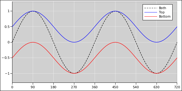
Equation 1c is obtained by summing the two previous equations. The waveforms are shown in figure 3.
.
Note: I use the word gorge in what follows, for reasons discussed in reference 1. The more-common but more-confusing term would be “charge”.
In more detail: Suppose we start out with Vc=0, which is not where it should be. It won’t stay there. During the transient, if the input voltage V is high, the bottom capacitor leaks, putting gorge on the top capacitor (but not the bottom), lowering Vc. If V is low, the top capacitor leaks, putting gorge on the bottom capacitor (but not the top), again lowering Vc.
Both capacitors operate with the correct polarity at all times after the initial transient.
The capacitance of the pair is half the capacitance of each component, in accordance with Ohm’s law in the usual way.
The voltage rating of the pair is equal to the voltage rating of each component. At the positive peak the top capacitor has to withstand the entire input voltage; 180 degrees later the bottom capacitor has to, as you can see in figure 3.
The following may help; if not, just ignore it: Suppose we temporarily freeze the input voltage at V=0. Then the floating node has some capacitance to ground. Consider the two (−) plates of the capacitors as forming one side of a double-sized capacitor, while the two (+) plates form the other side. That is to say, the floating node sees two capacitors in parallel.
More generally, suppose we unfreeze V, and instead assume V is driven by a low-impedance source. Then the floating node sees two capacitors in parallel, with the other terminal tied to V/2.
Leakage puts some gorge on this double-sized capacitor. In this sense we can speak of gorge “on” the floating node.
Keep in mind that one capacitor is leaking while the other is not, so the current through the pair cannot be divided into “leakage” current and “non-leakage” current.
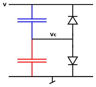
It may help to imagine each real capacitor as an ideal capacitor plus a separate leakage model, as shown in figure 4. This helps make the point that the leakage phenomenon is not magic; it just gorges and disgorges the capacitors in the usual prosaic way.