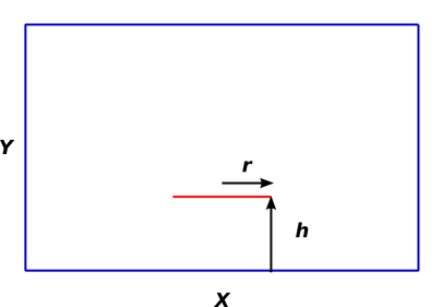
Figure 1: Capacitance of a Disk in a Room
Let’s see if we can figure out how an electrophorus works. This is quite an open-ended question. I find the analysis to be interesting without being overly complicated.
There may be some good explanations in the literature, but they seem to be hopelessly outnumbered by incomplete and confusing explanations. This version in reference 1 is typical, insofar as the diagram shows an unbalanced negative charge on the dielectric ... without showing what the field lines are doing. What’s worse, the distribution of charges on the moveable conducting plate is incorrect, presumably based on a seriously incorrect guess as to what the field lines are doing. Furthermore, some critical steps in the procedure are not diagrammed.
We start by doing some warm-up exercises, to establish some terminology and to build up a baseline understanding of exotic capacitors, including situations where there is both a mutual capacitance and a self-capacitance.
See reference 2.
Consider the situation in figure 1. There is a room with conducting walls (shown in blue). The floor of the room is X by X. The height of the room is Y. Centered over the middle of the floor is a thin metallic disk of radius r (shown in red). The disk is horizontal at a height h above the floor. There is a charge Q on the disk ... and correspondingly a charge −Q on the walls of the room. The disk is not very large, and the room is much wider than it is tall, so that X ≫ Y ≫ r.
Your mission, should you decide to accept it, is to find an algebraic expression for the voltage on the disk, as a function of h. Voltage is measured relative to the walls, which we designate to serve as “chassis ground”.
The disk has an insulating handle, so you can change h arbitrarily without changing Q.
Make whatever reasonable simplifying assumptions you like. (Replacing the conducting walls with non-conducting walls would not be considered reasonable.)
As a specific numerical instance, set
| (1) |
Charge up the disk to 1.5 volts using a battery, and then disconnect the battery. Raise the disk (maintaining constant Q during phase of the process). What happens to the voltage?
The usual jsd puzzle rules apply: Everything I have said is (to the best of my knowledge) true and non-misleading, although some details may be irrelevant. On the other hand, I have not told you everything I know. I have not told you the answer or even the method of solution ... and more importantly, the problem may be underspecified.
Again, the point is that after doing this warm-up exercise you should have a fighting chance of figuring out how an electrophorus works.
We boldly assume that the bottom of the disk combines with the floor to form a capacitor ... and that the top of the disk combines with the ceiling to form another capacitor. We have a circuit with these two capacitors in parallel.
Let Q1 be the charge on the bottom capacitor, and Q2 be the charge on the top capacitor. Let the corresponding capacitances be C1 and C2.
| (2) |
The two capacitors see the same voltage, so
| (3) |
The formula for a parallel-plate capacitor with an area A and a small gap g is
If we temporarily assume that we can ignore fringing fields, we can rewrite equation 3 as
| (5) |
hence
| (6) |
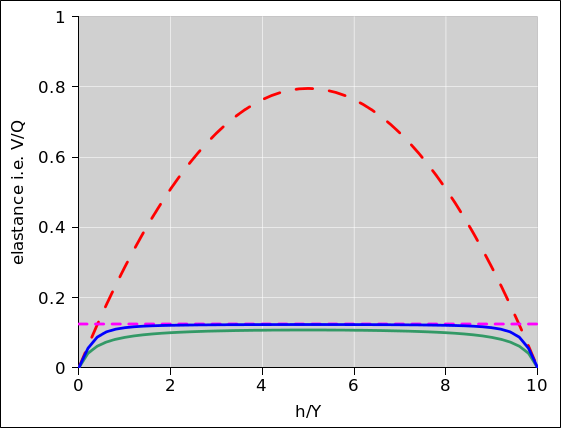
This result is shown by the dashed red curve in figure 2.
The result in section 2.2 is contingent on a number of assumptions.
Before we rely too much on the formula for a parallel-plate capacitor, we should consider what happens when there is a small disk in the middle of a large room. The capacitance is then dominated by the self-capacitance of disk, namely
| (7) |
A derivation of this formula can be found in reference 3.
The inverse self-capacitance is shown by the dashed magenta line in figure 2.
It should be obvious that under no circumstances can the capacitance of a disk be less than the self-capacitance. Comparing equation 4b to equation 7 implies we cannot possibly apply the parallel-plate capacitance formula unless the gap is quite small:
| (8) |
The solid green curve in figure 2 is an approximate interpolation between the two simple models. This interpolation is done by simply adding the two capacitances. This is surely an overestimate of the capacitance, and therefore an underestimate of the V/Q, i.e. a lower bound on the voltage we can achieve by manipulating the disk. The dashed curves in figure 2 serve as an upper bound. A general discussion of circular disk parallel-plate capacitor, including fringing fields, can be found in reference 4. There is no simple closed-form solution for the general case.
A better estimate is obtained by adding the two capacitances in quadrature. This is shown by the blue curve in the figure. This corresponds to using the Riesz (or Lebesgue) L2 norm. It sits in between simple addition (the L1 norm) and taking the lesser of the two contributions (the L∞ norm).
TODO: Compare this approximate algebraic approach to doing the actual integrals, as in reference 4.
This tells us that under a rather wide range of conditions, the height of the room is almost irrelevant. However, we would not have known this is we had not done the calculation in section 2.2. The relevant length-scales are either {r and h} or {r and Y−h} ... unless the disk is very large and/or the ceiling is very low. To say the same thing another way, the integral over the fringing fields converges quite quickly.
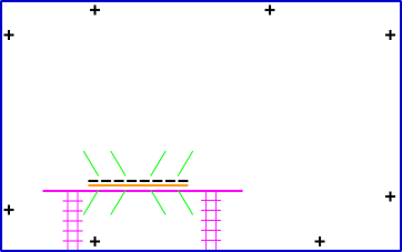
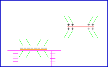
It is important that the dielectric sit on an insulating support, a goodly distance from any grounded object. In other words, in the situation shown in figure 3, the capacitance is dominated by the single-plate self-capacitance. Also note that the charge on the dielectric is not mobile. The electric field lines (shown in green) extend above and below the dielectric, heading off “to infinity” as they should in any self-capacitance situation.
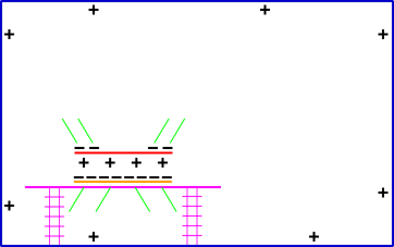
In the situation shown in figure 4, there is a tricky combination of two things going on. Half of the story involves treating the two plates as a parallel-plate capacitor, with the usual sort of mutual capacitance. Each plate of this capacitor bears a charge of ±4 units. The other half of the story involves treating the two plates together as if they were a single slightly-thicker plate, which exhibits a self-capacitance. This combined object bears a charge of −8 units.
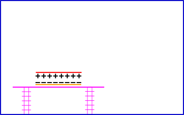
Figure 5 shows the situation after the moveable plate has been grounded, and after the grounding wire has been removed. The situation is entirely dominated by the two-plate mutual capacitance. The dielectric is at a slight voltage relative to ground, but since the capacitor gap is small and the capacitance is enormous, this voltage is rather small.
Once the dielectric has been charged up, it can under some conditions be used over and over again to induce charge on the moveable disk.
We start by considering the self-capacitance of a sphere:
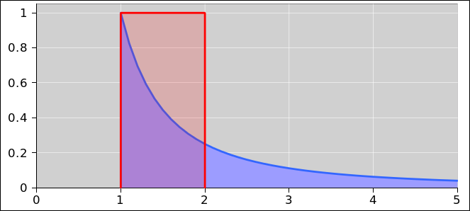
To make sense of equation 9c, we introduce the concept of effective gap, as follows: The field lines are most concentrated near the sphere, and then peter out as we get farther away. The concentrated field lines contribute the lion’s share to the total capacitance. We approximate the total energy in the field by overestimating the energy within a distance r of the surface while discarding the more distant contributions. This is shown in figure 7. The energy of the approximation (the red-shaded region) turns out to be exactly equal to the actual energy (the blue-shaded region).
That means we can consider the sphere to be analogous to a parallel plate capacitor, with a suitable area and gap:
| parallel-plate capacitor | spherical capacitor | |||
| Area: | The area of one plate | The total area of the sphere | ||
| (not counting the other plate). | (not counting the far-distant counterelectrode). | |||
| Gap: | The actual gap between the plates. | An “effective gap” | ||
| equal to the radius of the sphere. |
This can be considered a mnemonic for remembering the formula for the capacitance of a sphere. It produces the exactly-correct formula.
The usual way to calculate the capacitance of a thin disk is to start with a sphere and then transform it into an ellipsoid using suitable orthogonal coordinates. This can be considered a conformal transformation. See reference 3.
However, in the spirit of qualitative reasoning, we can get a rather good estimate of the capacitance of the disk using a simpler transformation. This is in some sense a scaling argument. We shrink the sphere in the Z direction but not in the X or Y direction.
We start from the parallel-plate capacitor formula (equation 4a) and the corresponding spherical-capacitor formula (equation 9c). Let’s see whether the disk upholds the same pattern, namely a capacitance in proportion to the area divided by some effective gap.
We find that the disk does uphold the pattern, except for a fudge factor of 4/π, if you set the effective gap equal to the radius. That’s off by less than 30%, which is not bad for a qualitative argument.
Another way of interpreting the same result is to say that the charge on the disk is more concentrated (not as evenly spread out) compared to the sphere, so the effective gap is smaller than you might have guessed, smaller by a factor of π/4.
Note that the appropriate area includes both sides of the disk.
This can be rather well solved using "qualitative reasoning". Some people are really good at qualitative reasoning, but others not so much. It is a skill that can be taught (and learned). This example can serve as nice teachable moment.
Specifically, consider the situation shown in figure 8. We have an asymmetric capacitor consisting of a moderate-sized flat disk somewhere near an enormous flat slab.
Step 1: My physics intuition says that when the disk is very near the slab, the capacitance is the same as it would be for a simple symmetric two-disk parallel-plate capacitor.
In this case "near" means g is very small compared to (π/8) r, where g is the capacitor gap and r is the radius of the disk.
Rationale: Draw the picture. Energy principles say that virtually all the relevant field lines will be in the gap. This accounts for virtually all the charge and virtually all the field lines. Experience playing with field-calculating software helps with this. See reference 5.
Step 2: When the disk is far away from the slab, the capacitance of the setup as a whole must be the same as the self-capacitance of the disk.
Rationale: For capacitances in series, we should be able to add the elastances (i.e. inverse capacitances). This is analogous to the rule for adding resistances in series. The slab has zero elastance (infinite capacitance) so the elastance of the overall situation is dominated by the elastance of the disk.
Step 3: Even if you don’t know how to find the exact result for an arbitrary-sized gap, you can get a good approximation by interpolating between the small-gap asymptote and the large-gap asymptote, as worked out in the previous steps. A preliminary version of this is discussed and diagrammed at www.av8n.com/physics/electrophorus.htm#fig-pre-electrophorus-plot
Step 4: The formula for a symmetrical capacitor is simple and well known for the case of a small gap. It is neither simple nor super-widely known – but still known (reference 4) – for an arbitrary-sized gap. We should be able to (a) invoke symmetry and (b) invoke the method of images to reduce the asymmetrical case to the corresponding symmetrical case ... /provided/ we keep track of various factors of two. The original situation should have half the elastance of the situation shown in figure 9.
The factor of 2 arises for a prosaic reason, namely that we are now measuring the voltage from the bottom disk to the top disk, rather from slab to disk. Twice as much V per unit Q means twice as much elastance.
By symmetry and/or by the method of images, that must be the same as
In the large-gap limit, the elastance here is just the series combination of the self-elastance of two disks. From this we obtain the final result, namely that the capacitance of the original asymmetrical situation (disk plus slab) should be double the capacitance of the corresponding symmetrical situation /with a double gap/.
In the small-gap case the two factors of two cancel out, so that disk + slab has the same capacitance as disk + disk (with the same gap) as expected. As the gap gets larger, the asymmetrical case starts to approach the large-gap asymptote twice as soon as you might have guessed by naively looking at the symmetrical formula.
Step 5: There is a piece of intuition that is implicit in all the previous steps. Consider the extreme large-gap limit. Zoom out your point of view so that the disk becomes essentially a single point. You know how the electric field of a point charge falls off with distance. You know that the Poyinting field energy goes like the square of the field. If you integrate this energy over all space, starting some not-too-small distance R away from the disk, then the integral converges. So the intuition is that whatever is going on in the far field never matters very much for electrostatics problems.
Now let’s consider what happens if we extend the plate to include the floor, ceiling, and four walls of a room. This raises questions about the “hall of mirrors” effect. I’m not worried too much about that, given that the overall charge is neutral. The images we see in the “hall of mirror” can be paired to form dipoles, and the dipole field falls off even faster than the monopole field. The lattice sum converges quite quickly, even with an infinitude of sources. Sure, it contributes a correction term in principle, but under a wide range of practical situations (electrophorus disk small compared to the size of the room) this won’t change the story in any qualitative way.
For more about the physics of capacitance, including odd-shaped capacitors, see reference 6